Research Article - Biomedical Research (2017) Volume 28, Issue 8
System for measurement of joint range of motion using inertial sensors
BS Mahima Sharma1,2, S Vidhya1* and Neelesh Kumar21VIT University, Vellore, Tamil Nadu, India
Accepted date: January 21, 2017
Abstract
Gait is a characteristic unique to every individual and it reflects the health status of an individual. Analysis of the parameters associated with movement can impart some knowledge regarding the gait characteristics of a person. Hence the knowledge of gait abnormalities can aid in assessment and treatment planning. Joint kinematics is one such measure which has clinical implications. The work done in this paper is an effort to study the existing technologies and to tap the potential of inertial sensors in estimating the range of motion (RoM) of the Knee and the Hip joints. This requires appropriate signal processing in order to extract the information with the help of an efficient Inertial Sensor Unit (ISU) with robust and easy to implement signal processing techniques at various stages.
Keywords
Gait analysis, Inertial sensors, Joint Range of Motion
Introduction
Locomotion is a distinctive attribute of animals that plays a major role in sustenance of life. The study of movement in humans and animals has hence been regarded as a fascinating area since the prehistoric times. The study of human movement also called Human Kinesiology provides a quick window into a person’s identity and body functionality since the movement pattern or gait is a commonly observed activity. Analysis of gait and its monitoring finds applications in several domains of life such as medical diagnostics, orthopedics and rehabilitation, sports training, biometrics and security systems [1]. Gait analysis involves study of the kinematic, kinetic and dynamic EMG parameters associated with gait. Standard gait analysis is generally carried out in specialized laboratories and is concerned with the measurement of body movements, forces and moments, energy expenditure, EMG (muscular activity) and spatio-temporal parameters including joint kinematics, trajectories, step length, cadence, step width, gait cycle phases, and gait speed that change throughout the gait cycle [2,3]. Clinical gait analysis ultimately aims in the diagnosis of gait impairments, determination of their causes, in deciding appropriate corrective actions and monitoring rehabilitation progress and also in fall detection [4].
The following three approaches [5] are used in gait analysis, individually or as a combination: Image capture and processing, non-wearable based Floor sensors and Bodymounted or wearable sensors. These approaches have inherent advantages and disadvantages. Video-based motion capture system has been regarded as the gold standard in gait analysis. It includes marker-based and marker-free systems. Advantages of Motion-capture based systems include: accuracy, real time analysis with automated and quick results, high image resolution and simultaneous recording of multiple events. The disadvantages include high equipment and computation cost, and limited analysis which is only restricted to laboratory settings. In the floor sensor-based approach, gait is measured using pressure sensors, force sensors and moment transducers fitted on the instrumented platforms. Analysis is performed as the subject walks on it. One advantage of this approach is that the system is unobtrusive. Disadvantages are same as that of Image processing based methods viz. high equipment and computation cost and limited analysis only under laboratory settings.
Although accurate results are provided by the above two approaches, factors [1] such as high cost of equipments, long initial setup time and post-processing time, complications in processing techniques and constricted environment pose as hindrance in efficient data recording. These problems can be mitigated with the use of Inertial sensors. Hence the third approach towards gait analysis involves the use of wearable sensors like encoders, magnetic sensors, potentiometers, electrogoniometers and inertial sensors. MEMS devices that are popular in the healthcare and well-being industry are being used in a plethora of applications including healthcare monitoring, assistance and rehabilitation, analysis of physical activities and environmental sensing [6]. Advantages of wearable sensors in gait analysis include: low cost, ruggedness, small size, portability, low power consumption and easy integration with other systems. MEMS based Inertial Sensors are made up of a combination of sensors, the most common being accelerometers, gyroscopes and magnetometers. The work done in this paper is an effort to tap the potential of inertial sensors in estimating the range of motion (RoM) of the knee and the hip joint. The sensors used in this work are accelerometers and gyroscopes. This combination of sensors can be referred to as an Inertial Sensor Unit (ISU). Thus, by processing the output of one or more inertial sensors individually, an inertial sensor unit can derive the joint angles by measuring the linear and angular motion.
Related works
The advantages of inertial sensors have sanctioned their use in different gait analysis applications. Different researchers have used inertial sensors in the control of intelligent orthosis or exoskeletons. Rocon et al. [7] used a triaxial inertial sensor consisting of accelerometer and gyroscope for the control of lower limb exoskeleton to measure angular acceleration, segment orientation, joint velocity, and joint angles, and to detect gait events using gyro signals. It was observed that for precise output, proper sensor attachment, alignment, calibration and drift correction are essential. Barbu [8] proposed a simple 1 DOF rehabilitation device with brushed DC motors as actuators. The Xsens MTw ISU was used along with an ISU module designed by the author that consisted of Memsic 2125 Accelerometer and ADXRS300 Gyro. The IMU provided a drift-free 3D orientation but the limitation observed was the complexity and high cost of Xsens MTw sensors. Doshi’s work [9] explored the potential of wearable technologies paving way to tele-rehabilitation. The author used inertial sensors to monitor stroke rehabilitation progress and this was observed to be advantageous over Constraint Induced Movement Therapy (CIMT). The WiTilt v2.5 sensor board (Triaxial Accelerometer MMA7260Q with Bluetooth) was used to quantify impaired arm usage with information obtained along the 3 axes of accelerometer and also to track rehabilitation of affected arm. Rahimi et al. [10] developed a system to capture whole-body mobility of patients with Parkinson’s Disease (PD) using the commercial FAB (Functional Assessment of Biomechanics™) inertial sensor by Biosyn systems.
A wearable gait analysis system using the commercial Shimmer sensor nodes, was developed by Anna et al. [11] to derive gait symmetry and normality. The system was observed to be advantageous when compared to Motion capture systems and other conventional techniques since it was economical, easily usable and interpretable. Another body motion analysis system was developed by Kan [12]. The author developed two wearable ISU nodes consisting of Triaxial accelerometer, Biaxial Gyroscope, Wireless sensor network (WSN) mote, a power supply circuit and an Integrated inverted-F antenna on a PCB (Printed circuit board) with intelligent power management. Seel et al. [13] used the commercial wireless Xsens Inertial sensor to estimate joint angles. The recorded inertial data was used for identification of joint axis coordinates and position. For joint angle measurement, a novel method was used wherein both angular rates were integrated around the joint axis itself. This angle when combined in a sensor fusion (using complementary filter) with a noisy but drift-free joint angle estimate calculated from the measured acceleration gives accurate results. Precise results were obtained in this system.
Another group of researchers, Maziewski et al. [14] used Shimmer sensors (with Triaxial accelerometer) for Activity Recognition. Wang et al. [15] developed a system based on inertial sensors for performing the TUGT clinical motility test (Time-Up and Go Test) and the end result was an automatic balance and gait analysis system. Other applications of Inertial sensors in gait analysis are in physical activity classification and recognition for purposes like monitoring of rehabilitation, body segment posture and orientation determination, gait phase detection, assessment of gait symmetry and gait normality, identification of gait characteristics, fall detection, estimation of energy expenditure, and extraction of spatio-temporal parameters like joint kinematics, trajectories, step length, cadence, step width, gait cycle phases, gait speed, etc.
Joint angle and range of motion
The lower extremity joint angles (hip, knee and ankle joint angles) are used in the clinical settings for diagnosis and treatment. They have been used to determine gait impairments, determine isometric strength of the joint [16], and to distinguish between different gait phases in a gait cycle [17].
Joint angle
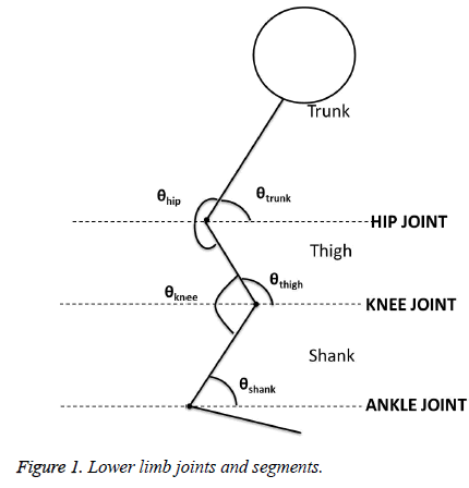
The human body can be considered as a link of rigid segments. The relationship between the adjoining segments can be quantified as the time rate change of the angle between them [18]. Any angular position information can be represented as segment/ absolute angles or as relative/joint/cardinal angles. The knee joint angle, which is a relative angle, can be represented relative to the two segments- Shank and Thigh. It is computed by subtracting the inclination angles of the thigh and shank segments. Similarly, the hip joint angle can be measured by taking the difference of the trunk segment angle and the thigh segment angle. Figure 1 illustrates the Lower limb joints and segments.
The Knee joint and the Hip joint angles can be computed using the formula given in (1) and (2).
θknee = | θthigh – θshank | (1)
θhip = | θtrunk – θthigh | (2)
Joint (range of motion) RoM
Range of motion (RoM) is a measure of angular movement at a joint that defines the joint flexibility. Range of motion estimation is a movement examination technique used for therapeutic intervention. For normal functional activities, The Knee and Hip Joint Flexion/Extension angle play a significant role. A restricted Joint RoM can affect the functioning of the entire lower extremity. For instance, when the knee flexion is reduced, it has reported to cause gait impairments, difficulties in squatting and stair-climbing. With impaired knee extension, gait can be functionally altered, causing difficulty in attaining closed packing in knee and trouble in running [19]. The normal Knee and Hip RoM ranges for Flexion/Extension are given in Table 1 as dictated by the American Academy of Orthopaedic Surgeons (AAOS) guidelines and other sources [20].
| Movement | Normal RoM |
|---|---|
| Knee Flexion | 0-135~150° |
| Knee Extension | 0-10~30° |
| Hip Flexion | 0-100~125° |
| Hip Extension | 0-10~30° |
Table 1. Knee and Hip joint RoM.
Methodology
Joint angle measurement
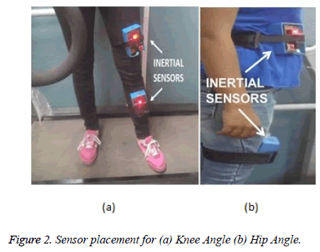
Knee angle was measured with two inertial sensors placed at the shank and thigh respectively. Calculation of the Hip joint angle was done by placing inertial sensors at the trunk and thigh segments respectively. Figures 2a and 2b show the sensor placement for computing the knee and hip joint angle respectively.
Typical RoM measurement
Active Knee RoM is measured from the lateral side of the subject's leg in a supine position. The leg is first brought to full extension, with the shaft extended maximally while maintaining a 0° angle between the femur and the tibia. The knee is then brought to full flexion with maximal bending of the knee and the angle is measured again, which gives the knee flexion angle. For the hip RoM, with the pelvis stabilized in the supine position, the knee is initially extended and the thigh is brought close to the trunk. The angle thus measured between the trunk and the thigh gives the hip flexion angle. The hip extension is measured as the angle between the trunk and knee while in the prone position, with the knee extended maximally. For the hip and knee RoM measured while walking, the corresponding maximal flexion and extension angles are noted.
Inertial sensor module
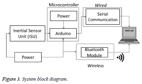
Two ISU modules, one with a single triaxial analog accelerometer ADXL335, and another ISU module with a combination of digital triaxial accelerometer (ADXL345) and gyroscope (L3G4200D) were developed to acquire data from the source. An Arduino based microcontroller was used for data acquisition purpose. The data obtained from the microcontroller was stored via. wired (USB serial based) and wireless means (via. Bluetooth transmission).
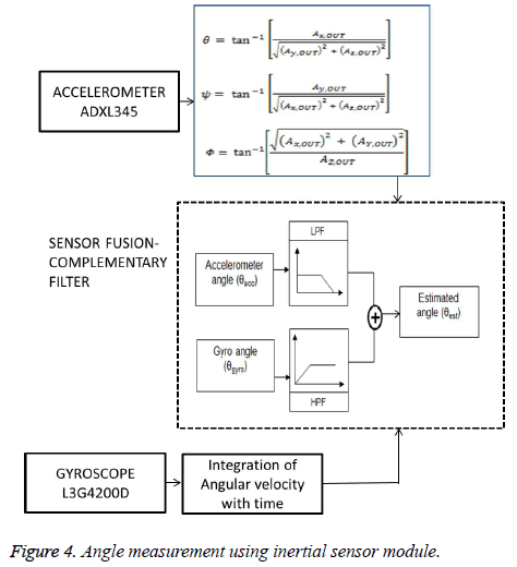
The stored data was used for offline analysis in the MATLAB software. The ISU module-1 data was pre-processed and hip and knee joint angles were obtained correspondingly. The measurement data obtained from ISU module-2 consisted of acceleration and angular velocity values. These were in turn used to deduce the angle individually. For a better result, the data from the accelerometer and gyroscope was combined using Complementary filter for sensor fusion. Figure 3 shows the System block diagram. The accelerometers and gyroscope were used to estimate the angles. For the accelerometer, the projection of the gravity vector along the x-, y- and z-axes is used to compute the tilt or inclination angles. Angle can be obtained from gyroscope by numerically integrating the angular velocity. To compensate the effects of the sensor’s individual weaknesses, a Complementary filter was used. Figure 4 illustrated angle measurement technique used to measure the knee angle.
The Complementary filter, which can be used when two different measurement sources estimate a single variable and the noise properties of these sources are such that one source shows high performance in the low frequency region and the other gives valid results in the high frequency region. This holds good for inertial sensors consisting of accelerometers and gyroscopes. In the complementary filter algorithm, the transfer functions of the accelerometer and gyroscope are distributed such that the sum of their filter coefficients is equal to 1. Complementary filter is advantageous due to its simplicity. Also, there is no need for statistical description of the noise signal and a simple analysis can be performed in the frequency domain [21].
Results and Discussion
With the inertial sensor modules placed at appropriate anatomical locations, the joint RoM can be estimated by computing the difference of the segment angles. For Range of motion, the Hip and knee joints are brought to the maximum flexed and extended positions (Table 2). These are compared with the Electrogoniometer which are used in a day to day basis in clinical settings. The ISU Module-1 data gives the RoM values directly obtained from the stand-alone accelerometer. ISU Module-2 data gives the Complementary filter result, which combines the accelerometer and gyroscope angular results. The inertial sensor modules were further analysed by placing them on the subject while walking at 1 km/h on a Treadmill. The results obtained using the two ISU Modules are tabulated in Table 3.
| Movement | Normal RoM | RoM of Subject (in Degrees) | RoM of Exoskeleton device | ||
|---|---|---|---|---|---|
| Gonio-Meter | ISU Module-1 | ISU Module-2 | |||
| Knee Flexion | 0-135~150° | 114° | 98.93° | 109.03° | 83° |
| Knee Extension | 0-10~30° | 5° | 9.8° | 5.72° | 9° |
| Hip Flexion | 0-100~125° | 92° | 78° | 82° | 83° |
| Hip Extension | 0-10~30° | 20° | 14° | 18° | 9° |
Table 2. Joint RoM results.
| Movement | Normal RoM during Walking | RoM of Subject | |
|---|---|---|---|
| ISU Module-1 | ISU Module-2 | ||
| Knee Flexion | 73.5° | 51.7° | 71.31° |
| Knee Extension | 0-10° | 9.8° | 5.72° |
| Hip Flexion | 32.5° | 18.83° | 25.39° |
| Hip Extension | 22.5° | 8.31° | 17.72° |
Table 3. Joint RoM results during walking.
The first module, consisting of an analog stand-alone accelerometer amounts to an error of 7.5675° when the measurements are made relative to the electrogoniometer results. In ISU Module-2, comprising digital inertial sensors, the RoM measurements are obtained with an average error of 4.0625°. For range of motion values obtained while walking on the treadmill, it was observed that although both the modules indicate normal RoM for a normal subject, ISU module-1 results are lower than that of ISU module-2. The higher error values contribute to the discrepancies in the RoM results.
In this work, upon comparing two different ISU modules, it was observed that ISU Module-2 gives better results due to the following reasons:
• It consists of Digital 3 axes accelerometer and Gyroscope compared to its counterpart ISU Module-1 consisting of only a single analog accelerometer.
• The weaknesses of gyroscope and accelerometer can be compensated with the use of sensor fusion algorithms like Complementary filter.
Since the study was conducted only on an exoskeleton device and a single subject, this limited analysis may mask the real results. This can be mitigated by testing the ISU Modules on a sizable number of subjects.
Conclusion
Inertial sensors have found acceptance in the healthcare setting due to their reliability and portability. The inertial sensors used in this study were found to have convenience in usage due to their compactness and size. The preliminary tests to determine the knee and hip joint range of motion using the developed inertial sensor modules show that the angular values are comparable to that obtained using electrogoniometers, and the values lie within the normal RoM ranges. However, the preliminary test results as performed in his study are subjected to errors. An average error of 7.5675° observed in ISU Module-1 as against the 4.0625° average error in ISU Module-2 indicate that the ISU module-2 performs better than the first module. Further, the errors in the ISU modules can be reduced by implementing more effective but mathematically intensive sensor fusion algorithms. Further research should include a wider population size to examine the accuracy of the developed sensor modules.
Acknowledgment
The authors would like to express their thanks and acknowledge the support extended by the researchers in CSIRCSIO (Central Scientific Instrument Organization) research laboratory, Bio-medical Department, Bio signal lab and Gait Lab, Chandigarh, India.
References
- Tao W, Liu T, Zheng R, Feng H. Gait analysis using wearable sensors. Sensors 2012; 12: 2255-2283.
- Andrejiová M, Dolná Z, Simsik D, Kimáková Z. An analysis of temporal and spatial parameters of human gait. Int J Engi 2012.
- Groth H, Novak S. Examination of the Reliability and Validity of Rancho Los Amigos Observational Gait Analysis, Master Thesis, Grand Valley State University, 1999; In:
- Clinical Gait Analsyis and its role in Treatment Decision making, 2015.
- Muro-de-la-Herran A, Garcia-Zapirain B, Mendez-Zorrilla A. Gait Analysis Methods: An Overview of Wearable and Non-Wearable Systems, Highlighting Clinical Applications. Sensors 2014; 14: 3362-3394.
- Ciuti G, Ricotti L, Menciassi A, Dario P. MEMS Sensor Technologies for Human Centered Applications in Healthcare, Physical Activities, Safety and Environmental Sensing: A Review on Research Activities in Italy. Sensors 2015; 15: 6441-6448.
- Rocon E. Application of inertial sensors in rehabilitation robotics. Proceedings of the 2007 IEEE 10th International Conference on Rehabilitation Robotics, 2007.
- Barbu DM. Sensors used for biomechanical rehabilitation of the paraplegic leg. Annals Oradea University 2015.
- Doshi SS. Applications of inertial measurement units in monitoring rehabilitation progress of arm in stroke survivors. Master’s Thesis 2011.
- Rahimi F, Duval C, Jog M, Bee C, South A, Edwards R, Boissy P. Capturing Whole-Body Mobility of Patients with Parkinson Disease Using Inertial Motion Sensors: Expected Challenges and Rewards. In Proceedings: 33rd Annual International Conference of the IEEE EMBS, 2012.
- Anna AS, Wickström N, Eklund H, Tranberg R, A wearable gait analysis system using inertial sensors Part II: Evaluation in a clinical setting. BIOSIGNALS 2012 - Proceedings of the International Conference on Bio-Inspired Systems and Signal Processing, Algarve, 2012.
- Kan YC. A Wearable Inertial Sensor Node for Body Motion Analysis. IEEE Sensors J 2012; 12: 3.
- Seel T, Raisch J, Schauer T. IMU-Based Joint Angle Measurement for Gait Analysis. Sensors 2014; 14: 6891-6909.
- Maziewski P, Kupryjanow A, Kaszuba K , Czyzewski A. Accelerometer signal pre-processing influence on human activity recognition, In Proceesings: Signal Processing Algorithms, Architectures, Arrangements, and Applications Conference Proceedings, Poland, 2009.
- Wang WH, Chung PC, Yang GL, Lin CW, Hsu YL , Pai MC. An Inertial Sensor based Balance and Gait Analysis System, In Proceedings: 2015 IEEE International Symposium on Circuits and Systems, Lisbon, 2015.
- Haffajee D, Moritz U, Svantesson G. Isometric Knee Extension Strength as a Function of Joint Angle, Muscle Length and Motor Unit Activity. Acta Orthop Scandin 1972; 43: 138-147.
- Barton JG, Lees A. An application of neural networks for distinguishing gait patterns on the basis of hip-knee joint angle diagrams. Gait Posture 1997; 5: 28-33.
- Tözeren A. Human Body Dynamics: Classical Mechanics and Human Movement. 2000.
- Shah N. Clinical suggestion Increasing Knee Range of Motion using a unique sustained method. North Am J Sports Phy Therapy 2008.
- American Academy of Orthopaedic Surgeons , “Average Ranges of Motion”
- Higgins WT. A Comparison of Complementary and Kalman Filtering. IEEE Transact Aerosp Elect Sys 1975.


