Research Article - Biomedical Research (2018) Artificial Intelligent Techniques for Bio Medical Signal Processing: Edition-II
Meta-data based secret image sharing application for different sized biomedical images
Arunkumar S1*, Subramaniyaswamy V1, Karthikeyan B2, Saravanan P1 and Logesh R1
1School of Computing, Sastra University, Tamilnadu, India
2Department of IT, Viswajyothi College of Engineering and Technology, Kerala, India
Accepted date: August 28, 2017
DOI: 10.4066/biomedicalresearch.29-17-751
Visit for more related articles at Biomedical ResearchAbstract
Usually in image sharing schemes, shares are generated first for a given secret image and then embedded into cover images to produce stego images. These two steps are done sequentially. There exist some relationship in the first step, the size of the secret image and size of the shares which are derived from them. In the proposed method, these two steps are done concurrently. A cover image is chosen and according to its embedding capacity, share is generated and subsequently embedded into chosen cover to produce the stego image. This process is repeated till all the image portions are embedded. While generating share, meta-data (i.e.) header is created for each shares and appended to shares before being embedded. At the destination end, shares are extracted from each stego images and are reassembled into a single original secret image according to the meta-data present in each share. Methods available in the literature embeds uniform sized secret image into cover images of uniform sizes. Using proposed method different sized secret images have been embedded into cover images of varying sizes.
Keywords
Image sharing, Different sized image, Batch steganography, Least significant bit, Compression
Introduction
Shamir et al. designed a Secret Sharing (SS) method to share a secret key where secret key is an integer valued which can be divided into many integer values according to the polynomial equation [1,2]. SS methods are used for many real world application [3,4]. In real life, SS schemes can be applied. Consider this scenario. A country does not want to give the supreme power of giving permission to the use of nuclear weapon in a war. But instead, this power rest on three persons, president, prime minister and the defence minister of that country. At least two out of three must agree to the idea of invocation of nuclear war [5]. SS scheme can be applied to images as well. This is referred as Secret Image Sharing (SIS). This is reported first in [6]. Later SS schemes are applied on the other types of cover as well, i.e., test, audio and video [7]. Many SIS schemes have been proposed so far using different concepts [8,9].
In data communications networks, original data is divided into small chunks called packets by segmentation process when it cannot be transmitted as single packet. Process done at the source end needs to be computed in a reversed order at the destination end to reconstruct the original data from packets [10]. Sometimes, information to be transmitted called payload can be compressed and if need be can be encrypted also [11]. In data communications networks, after original data are segmented into packets. It is encoded as signals and transmitted across the communication medium to reach the destination. This can be modified for steganography. In SIS, after images are divided into shares, it can be embedded into a chosen cover image. So encoding of packets in data communication is correlated with embedding of share in steganography in our proposed method.
Related Works
Thien et al. describes the method for construction of shares from a secret image. Size of the constructed share is smaller than the secret image. This share looks like a random noise image. If shares are sent as such, there will be suspicion. To avoid this, shares are embedded into a cover image to produce a stego image. If t numbers of shares are produced, then size of the share is 1/t of secret image. Size of the cover image which is chosen for embedding these shares must be either 2 times or 4 times the size of share [12]. Wu et al. modifies the paper in such a way the size of the share is 1/t but the size of the stego image is also 1/t [12,13].
Yuan et al. described methods for sharing a binary secret image into multi cover images. For sharing a secret image, four cover images of similar size are chosen. A binary matrix is calculated by XORing LSB planes of all the cover images. To embed secret image into cover, each secret pixel Ai, j of secret image is compared with Bi, j of binary matrix, if both are same, no operation is done and next secret pixel are examined, otherwise using gradient measure, particular cover image is chosen for embedding this particular secret pixel into Ci, j of the chosen cover image. Using LSB matching secret pixel in embedded into LSB plane of a cover image. But in the recovery process all LSB plane of the stego images are simply XORed [10]. Chen et al. describes methods for sharing multiple images of different sizes. Apart from describing to how to recover origin image from the share, this paper also describes how to recover secret images even when image shares are corrupted or noise are added in the shares. A random image is calculated from all the secret images. The size of the random image is equal to the size of larger images. The random image is used both while creating a share from the secret image and recovering secret image from share [11].
Proposed Method
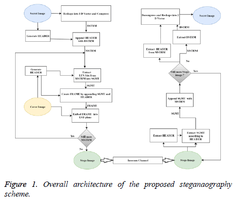
Proposed method comprises of four algorithm, they are Message Stream Generation (MSG) which generates one dimensional MSTRM vector for the given secret image, LSB Embedding Algorithm (LEMA) which generates FRAMEs from MSTRM which is then embedded into cover to produce stego images, LSB Extraction Algorithm (LEXA) which extracts FRAMEs from the stego images and are concatenated into one dimensional MSTRM vector and Secret Recovery (SR) algorithm which reconstruct the secret image from MSTRM according to HEADER information. Overall functioning of this proposed method is illustrated in the Figure 1.
MSG algorithm
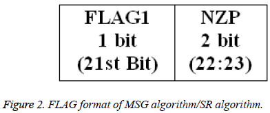
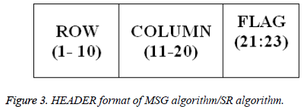
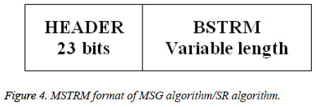
Secret image is taken as input from the user. Dimension of the image is determined based on its rows and columns which are used at the destination end for the reconstruction. Given secret image is reshaped into 1-D vector as BSTRM. BSTRM may be compressed or not. If BSTRM is compressed, few zeros are padded into BSTRM to ensure that equal number of bits is embedded in each pixel. FLAG, HEADER, and MSTRM are computed as shown in Figures 2-4. FLAG1 is used to specify if compression is done or not. NZP is used to specify the number of zero padded.
Input: Secret image
Output: MSTRM
Step 1: For the given secret image, row and column are calculated. These are used at the receiver end to reshape secret image.
Step 2: Given secret image is reshaped into 1-D vector, It is called BSTRM.
Step 3: FLAG1is for compression and NZP is for padding. FLAG1 set to 1 if compression is done, otherwise set to 0.
Step 4: If FLAG1 is 1, dictionary is generated. Then BSTRM is compressed using Huffman compression algorithm. Generated dictionary is sent to the receiver.
Step 5: N Number of Zero (NZP) is padded into BSTRM, N is calculated such that the length of BSTRM is congruent to 1, 2, 3 or 4, this is according to number of LSB bits are embedded.
Step 6: FLAG, HEADER and MSTRM are generated as shown in Figures 2-4.
LEMA algorithm
MSTRM is taken as input. A cover image is chosen and its Embedding Capacity (EC) is computed. If entire MSTRM can be embedded into this image, MSTRM is considered as SGMT and FRAME is formed and it is embedded into the cover image to produce stego image. If not, EC-48 bits are extracted from MSTRM and are considered as SGMT and FRAME is formed and it is embedded into cover image to produce stego image. These steps are repeated till entire MSTRM bits are embedded. FLAG2 is used to specify if it is a last FRAME or not.
Input: MSTRM
Output: Stego images
Step 1: A cover image is chosen. Embedding Capacity (EC) of the cover image is computed.
Step 2: If length of MSTRM is less than EC-48 then do
2.1 Entire MSTRM is assigned to SGMT
2.2 Length of the SGMT (SLEN) is calculated.
2.3 FLAG2 is assigned to ‘1’
2.4 Sequence number is incremented
Step 3: If condition in step 2 is not correct then do
3.1 Length of the SGMT (SLEN) is calculated by SLEN=EC-48
3.2 SLEN bits are extracted from MSTRM into SGMT.
3.3 FLAG2 is assigned to ‘0’
3.4 Sequence number is incremented
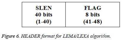
Step 4: FLAG, HEADER and FRAME are generated as shown in Figures 5-7.
Step 5: This FRAME is embedded into the chosen cover image.
Step 6: If length of MSTRM is not zero, then above steps are repeated.
LEXA algorithm
Stego images are taken as input. First 48 bits are extracted from the stego images which are a HEADER which contains information as shown in Figures 5 and 6. SLEN number of bits are extracted from the stego images and assigned into cell array with SQN_NO as index. This step is repeated for all the stego images. Then this cell array is converted into 1-D row vector which is called MSTRM.
Input: Stego images
Output: MSTRM
Step 1: 48 bit HEADER is extracted from the stego images. It contains information as shown in Figures 5 and 6.
Step 2: SLEN number of bits are extracted from the stego image and assigned into cell array MSTRM with SQN_NO as index.
Step 3: If still more Stego images are there, above steps are repeated.
Step 4: MSTRM which is in the form of cell array is converted into 1-D row vector.
SR algorithm
MSTRM is taken as input. ROW, COLUMN, FLAG1 and NZP are derived from the first 23 bits as shown in Figures 2 and 3. Decompression and removing few zeros are carried on BSTRM according to the FLAGE1 and NZP fields. BSTRM is reshaped into 2-D array according to ROW and COLUMN fields and is encoded into an image.
Input: MSTRM
Output: Secret image
Step 1: HEADER and BSTRM are derived from the MSTRM as shown in Figure 4.
Step 2: Information like ROW, COLUMN, FLAG1, NZP, are derived from the HEADER shown in Figures 2 and 3.
Step 3: NZP number of ‘0’ are removed from BSTRM.
Step 4: If FLAG1 is 1, Decompression needs to be done. Dictionary is received from the sender; BSTRM is decompressed using Huffman compression algorithm.
Step 5: BSTRM is reshaped into 2-D vector according to row and column and encoded as image.
Experimental Results
In this section, performance of our proposed method is compared with the similar schemes like Thien et al., Wu et al., Yuan et al., and Chen et al. [10,11,14,15]. Data set is created by us that is downloaded from internet and resized according to our needs. Parameter used for comparing our method is size of secret image and size of cover images. First three schemes take the secret image size of 512 × 512. Fourth scheme takes three different sizes. But ours is not limited to any size. This relationship is depicted in the Table 1. In the available literature, size of shares and stego images are related to the size of secret image. But in our proposed method, there need not be any relation in terms of sizes among cover images and between secret image and cover image. Two case studies are done for embedding secret image into cover image. For the evaluation of the proposed algorithms, we also utilized DICOM medical image dataset for the estimation of performance over existing approaches.
| Schemes | Size of secret image | Type of image sharing schemes | Size of cover | Size of shares | Size of stego image |
|---|---|---|---|---|---|
| Thien et al. | 512 × 512 | (t, n) | All uniform | 1/t of secret image | 2/t or 4/t of Share |
| Wu et al. | 512 × 512 | (t, n) | All uniform | 1/t of secret image | Same as share |
| Yuan et al. | 512 × 512 | (n, n) | All uniform | Same as secret image | Same as secret image |
| Chen et al. | 512 × 512 256 × 256 128 × 128 |
(n, n) | According to secret image size | Same as secret image size | Same as secret image size |
| Proposed | Any size | (n, n) | Different sizes | According to cover image size | Same as cover image |
Table 1. Comparison of Size of secret image and cover image.
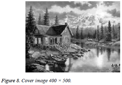
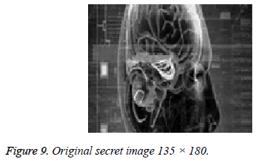
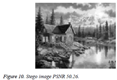
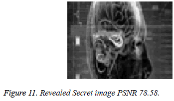
In the first case study, one share is generated from one secret image which is embedded into one cover image. This is explained by the following figures. Figure 8 shows the cover image that is used for embedding the secret image. Its size is 400 × 500. Figure 9 shows the original secret image, its size is 135 × 180. Figures 10 and 11 shows the stego image and the revealed secret images respectively. There is no relation between size of original image and cover image.
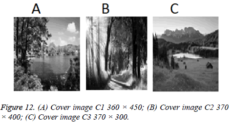
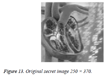
In the second case study, three shares are generated from one secret image which is embedded into three cover images. Figures 12 (A-C) shows three cover images of size 360 × 450, 370 × 400 and 370 × 300. Figure 13 shows the secret image of size 250 × 370. In this case also, there is no relationship in terms of size among cover images and between secret image and cover image.
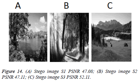
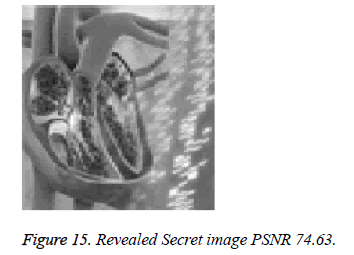
Figures 14 (A-C) shows three stego images generated from Figures 12 (A-C). PSNR of stego images are 47.08, 47.11 and 52.11. Figure 15 shows revealed secret image and its corresponding PSNR is 74.63.
Above experimental results shows that proposed scheme is used for embedding differently sized secret image into cover image of different size. The PSNR of revealed secret images are 74.63 and 78.58 which are better than existing approaches.
Conclusion
Secret image is preprocessed before shares are generated. In the preprocessing stage, image is first read into 2-D vector and the reshaped into 1-D vector. Meta data i.e., header for the secret image is generated such that it contains information like number of row and column of secret image (i.e., which is useful in reshaping the 1-D vector to 2-D vector in the recovery stage after all shares are assembled) and some field for denoting if compression is done on the 1-D vector or not. After preprocessing, shares are generated according to the chosen cover image and embedded into it. At the recovery stage, shares are extracted from stego images and reassembled into 1-D vector first and then reshaped into 2-D vector according to the details in the meta-data. Thus an efficient method is designed to send secret images of different sizes into cover of varying sizes.
References
- Shamir A. How to share a secret. Communications of the ACM 1979; 22: 612-613.
- Blakley GR. Safeguarding cryptographic keys. Proc National Comp Confer 1979; 48: 313-317.
- Iftene S. Secret sharing schemes with applications in security protocols. Sci Ann Cuza Univ 2006; 16: 63-96.
- Martin KM. Challenging the adversary model in secret sharing schemes. Coding and Cryptography II, Proceedings of the Royal Flemish Academy of Belgium for Science and the Arts 2008; 45-63.
- Trappe W, Lawrence CW. Introduction to cryptography with coding theory. Pearson Education, India 2006.
- Naor M, Adi S. Visual cryptography. Workshop on the theory and application of cryptographic techniques. Springer Berlin Heidelberg 1994.
- Liu YX, Ching NY, Po HY. Reducing shadow size in smooth scalable secret image sharing. Security Communication Networks 2014; 2237-2244.
- Wu X, Wei S. Secret image sharing scheme with authentication and remedy abilities based on cellular automata and discrete wavelet transform. J Systems Software 2013; 1068-1088.
- Eslami Z, Zarepour AJ. Secret image sharing with authentication-chaining and dynamic embedding. J Systems Software 2011; 803-809.
- Yuan H-D. Secret sharing with multi-cover adaptive steganography. Inform Sci 2014; 254: 197-212.
- Chen C-C, Jun-LC. A new Boolean-based multiple secret image sharing scheme to share different sized secret images. J Inform Security Appl 2017.
- Tanenbaum AS. Computer networks (4th ed). Prentice Hall, New Jersey, United States 2003.
- Stallings W. Cryptography and network security: principles and practices. Pearson Education, India 2006.
- Thien C-C, Ja-CL. Secret image sharing. Computers Graphics 2002; 765-770.
- Wu Y-S, Chih-CT, Ja-CL. Sharing and hiding secret images with size constraint. Pattern Recognition 2004; 1377-1385.
