Keywords |
| Human, Hazards gas, GSM, Environment. |
Introduction |
| The ardent passion towards contributing to the society in order
to save human lives was the main reason behind the origin of
this project. Various articles which stated the numerous
cessations of human lives while attempting to treat
underground sewers intrigued our team to develop the model
[1,2]. For those who work in atmospheres that could be
hazardous to their health, selecting the right gas detector could
be the single most important decision they could ever make.
Their life could hinge on that decision so it is critical that the
user make him aware of the hazards that could be encountered
and the proper sensors to protect them. Data gathered in the
late seventies and early eighties indicated that 65% of all those
who died in confined spaces were unaware that the space they
were entering was a potential hazard. Over 50% of confined
space deaths occur to the rescuers and over one third of the
fatalities occurred after the space was tested and declared safe
and the gas detector was removed. |
| Gas detectors have been around for a long time, starting with
that infamous methane sniffing canary, which sadly was a oneshot
device, which when subjected to methane, tended to die
rather quickly with no audio and visual alarm capabilities other
than being slightly cheap and a total lack of motion.
Fortunately technology has advanced significantly and we find ourselves at this point in time with some very sophisticated
electronic equipment. But even the most sophisticated
technology is useless if the sensors used are unable to detect
the gases present. |
| Such references and may more throw light on the fact that the
sewer gases contribute a major role in the mortality rate. The
overall causal ratio may be small in comparison with others,
but is still not a good reason to ignore the situation as life,
however small it may be still has to be valued. |
| Tragedies like this frequently happen when gas monitors either
are used improperly or not used at all. Manufacturers tirelessly
work to make their instruments easier to use in an effort to
eliminate such tragedies. But no matter how user-friendly the
instruments become, if employees do not use them properly,
injury and death on the job will continue to occur. Deciding to
use a gas detector is a smart thing to do. These factors formed
the basis behind the origin of the paper. |
| Sewer gas is a complex mixture of toxic and nontoxic gases
produced and collected in sewage systems by the
decomposition of organic household or industrial wastes,
typical components of sewage. Sewer gases may include
hydrogen sulfide, ammonia, methane, carbon monoxide, sulfur
dioxide, and nitrogen oxides. Improper disposal of petroleum products such as gasoline and mineral spirits contribute to
sewer gas hazards. Sewer gases are of concern due to their
odor, health effects, and potential for creating fire or
explosions. |
| In developing countries like India, the sewers are still being
cleaned by unskilled laborers. Situations may arise where the
hazardous gases emitted by the sewage endanger their lives.
Furthermore, a similar situation may arise during the process of
coal mining where the miners may get exposed to such harmful
gases, a highly concentrated exposure of which, may even lead
to their death. Thus an efficient method to detect the presence
of such harmful gases becomes a necessity. |
| Our prime objectives are: |
| • To track the presence of hazardous gases, the most
threatening amongst them namely carbon monoxide and
methane present in trenches. |
| • To identify the safe limits of these gases and calculate the
level in that situation. |
| • Concentration of these toxic gases present in the air is
identified accurately in ppm (parts per million). |
| • To warn the workers about the potential threats that they
might face on account of exposure to such gases above a
safe limit by sending the effect of the gas at that level
through GSM technology. |
Related work |
| In 2014, Sunny, et al. [3] proposed a new feature technique
called average slope multiplication to quantify individual
gases/odours using dynamic responses of sensor array. The
ASM approach is a data pre-processing technique based on
multiplying the response and recovery data by the respective
average slope. The proposed method thus utilizes the new
developed feature ASM in the first stage and the specially
designed neural quantifiers in the next subsequent stages. ASM
is thus used to increase the accuracy in quantification of gases. |
| Ozmen and Tekce [4] presented a system which is made of an
array of eight phthalocyanine-coated QCM sensors and an
ANN to find the corresponding composition of a gas mixture.
The system is tested with the following gas mixtures: (1)
ethanol–acetone,(2)ethanol–trichloroethylene, (3) acetone–
trichloroethylene. The quartz crystal microbalances (QCM)
also called acoustic sensors are widely used for detecting the
change of resonant frequency of each sensor as a function of
gases. |
| In 2011, Ravi Kumar, et al. [5] laid before a new soft
computational approach for discrimination of gases. The raw
data obtained from the responses of oxygen plasma treated
thick film tin oxide sensor array exposed to different gases is
subjected to wavelet transform and appropriate coefficients
were selected using multi scale principal component analysis
(MSPCA). The network was found to identify the gases with a
high success rate. |
| Gulbag A and Temurtas F [6] put forward an Adaptive Neuro-
Fuzzy Inference System (ANFIS) for quantitative identification of individual gas concentrations in their gas mixtures. The
Quartz Crystal Microbalance (QCM) type sensors were used as
gas sensors. The components in the mixture were quantified by
applying the steady state sensor responses from the QCM
sensor array as inputs to the feed forward neural networks.
Acetone and trichloroethylene were evaluated in this study. |
| Capone S, et al. [7] proposed an array of highly sensitive and
mechanically stable gas sensors based on different sol-gel
fabricated Pd-doped SnO2 nanocrystalline thick films which
were used to detect concentrations of the range 0-100 ppm CO,
0-4000 ppm CH4 at 50% relative humidity. The selectivity of
the Pd content had been modulated by varying the percentage
of the Pd content. Principal Component Analysis as pattern
recognition and Principal Component Regression as multi -
component analysis method have been used to analyze the
mixtures. |
| Jing L, et al. [8] applied the principle of electronic nose system
in artificial olfactory system which combines gas sensor array
and artificial neural network recognition. The research
involved experimental configuration method of low
concentration gas, input, output and hidden layer element
determination method. The system was able to portray lower
error rate in quantitative recognition. |
| In 2013, Sunny, et al. [9] came up with a new method for
classification of gases/odours called average slope
multiplication (ASM) using dynamic characteristics of thick
film gas sensor array. The ASM approach is a data preprocessing
technique based on multiplying the response and
recovery data by the respective average slope. ASM reported
superior identification of gases than principal component
analysis (PCA) technique |
| In 2013, Khalaf W [10] pointed out in Sensor array system for
gases identification and quantification that a practical
electronic nose for simultaneously estimating many kinds of
odour classes and concentrations. The multi-input/multi-output
function is decomposed into multiple many to one tasks and
ensembles are used to implement them one after the another.
An ensemble represents a special kind of odour and realizes the
relationship between the sensor array responses and the
represented odour concentrations. The ensemble with the
smallest relative standard deviation (R.S.D) finally gives the
label and concentration of an odour sample. |
| Dae-Silk Lee, et al. [11] designed a sensor array with nine
discrete sensors integrated on a substrate to recognize the
species and quantify the amount of explosive gases. The
sensors were designed in such a way to produce uniform
thermal distribution and a broad sensitivity to low
concentrations through the use of nano-sized sensing materials
with high surface areas. Methane, propane and butane are some
of the common explosive gases. |
| A review of the pattern analysis of machine olfaction was laid
before by Gutierrez-Osuna R [12] a member of IEEE. Pattern
analysis constitutes a critical building block in the development
of gas sensor array instruments capable of identifying and
measuring volatile compounds. Summary and guidelines for using the most widely used pattern analysis techniques like
neural networks, chemometrics were proposed along with
research techniques that are at the frontier of sensor based
machine olfaction. |
Proposed Method |
| A gas detecting system is developed to protect the life of
trench workers from toxic gases. The system is designed in
such a way to detect the presence of carbon monoxide and
flammable gases. The most commonly found flammable gas in
trenches is methane. The system uses two sensors namely
Mq-2 and Mq-7 for the detection of these gases in air. An
Arduino board containing an Atmega 328 microcontroller is
used for processing. Arduino senses the environment by
receiving inputs from the two sensors, and affects its
surroundings by controlling the actuators. The actuators used
are an alarm and a LED light. The actuators are configured in
such a way they light up or give out a warning noise only if the
gases present in air exceed the threshold value. |
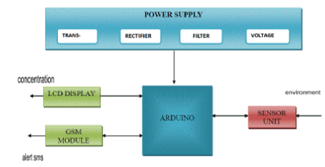
| The whole system is developed using the Arduino
programming language in the Arduino development
environment. A GSM shield is used to alert the user about the
presence of toxic gases using text messages. It can also be used
to alert co-workers or rescue workers to help the users in case
of an emergency. Given below is the basic system’s
architecture Figure 1. |
| The components present in the gas detecting system are: |
| • Power Supply Unit |
| • Sensor Unit |
| • Arduino |
| • Lcd Display |
| • Buzzer with driving circuit |
| • GSM unit |
Power supply circuit |
| The power supply units are designed to convert high voltage
AC mains electricity to a suitable low voltage supply for
electronic circuits and other devices. The power supply unit in
the gas detecting system is used to convert the 230V
Alternating current from the mains and provide the electrical
components with the required regulated 5V direct Current. The sensors, arduino board and the LCD display needs a regulated
power supply but the GSM modem contains a inbuilt voltage
regulator and hence does not need the power supply unit. |
| The sensors, arduino board and the LCD display needs a
regulated power supply but the GSM modem contains a inbuilt
voltage regulator and hence does not need the power supply
unit. |
| In the circuit as seen in Figure 2A, the transformer of 230v/
15-0-15v is used to perform the step down operation where a
230V AC appears as 15V AC across the secondary winding.
The rectifier is used to convert the Alternating Current (AC) to
Direct Current (DC) with the use of four diodes. This process
is known as rectification. The filtering circuit is used to
smoothen out the circuits so that it doesn’t damage even the
most sensitive of the circuits. Capacitor is introduced into the
circuit to accomplish the filtering process. The voltage
regulator is used to maintain a constant voltage level which is
being supplied to devices. |
Sensor circuit |
| A sensor is a transducer whose purpose is to detect some
characteristic of its environment. It detects any change in
events or change in quantity and provides an output as an
electrical signal. The two metal oxide semiconductors used are
MQ-7 for the detection of carbon monoxide and MQ-2 for the
detection of flammable gases. |
| The sensors can work with very less amount of power supply
and hence it makes them portable. The sensors contain 6 pins,
4 of them are used to fetch signals and the other two are used
for providing heating current. Optimal heating current is
needed for the working of the sensor. The sensors are
connected to a power supply of 5V which provides the required
circuit voltage for the proper functioning of the sensors. The
sensor unit detects the change in environment and reports it to
the Arduino in the form of electrical signals. |
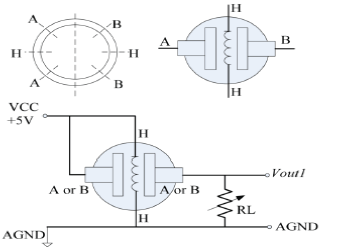
| As seen in Figure 2B, the preferred wiring is to connect both
'A' pins together and both 'B' pins together. It is safer and it is
assumed that is has more reliable output results. In the picture,
the heater is for +5V and is connected to both 'A' pins. This is
only possible if the heater needs a fixed +5V voltage. The
variable resistor in the picture is the load-resistor and it can be
used to determine a good value. A fixed resistor for the loadresistor
is used in most cases. |
Arduino-sensor circuit |
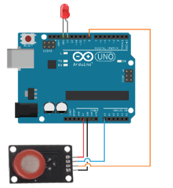
| Arduino is used for the processing of the electrical signals
received from the two sensors. The connections between the
Arduino and the sensor board are shown in the figure 2C. The
black wire indicates the ground connection and the red wire
indicates 5V circuit voltage. The analog output from the sensor
is connected to the analog input pin in the Arduino. Similarly
the digital output from the sensor is connected to one of the
digital input pins. |
| GND of Arduino to GND of sensor |
| 5V of Arduino to 5Vv of Sensor |
| Analog O/p of sensor to any one of the analog ports of Arduino |
| Digital O/p of sensor to any one of the digital pins of Arduino. |
| Figure 2C represents the Sensor and Arduino Connection. The
Arduino is made to read the analog output from the sensor
using the analogread () function. The analog read function
reads the value from the specified analog pin. The Arduino
board contains a 6 channel bit analog to digital converter. This
means that it will map input voltages between 0 and 5 volts
into integer values between 0 and 1023. The syntax of analog
read function is analog Read (pin) where pin is the number of
the analog input pin to read from. If the analog input pin is not
connected to anything, the value returned by analogRead ()
will fluctuate based on a number of factors (e.g. the values of
the other analog inputs, how close your hand is to the board,
etc.) Setup () and loop () are the two methods needed for a sketch to start. Hence the two methods are called as bare
minimum. The setup () function is called when a sketch starts
so it is used to initialize variables and pin modes. The pins
present in the Arduino are configured to behave as input or
output using the pin mode() function. The syntax for the
function pin mode is Pin Mode (pin, mode) where pin is the
number of the pin whose mode is to be set and mode is
INPUT/OUTPUT [13,14]. |
| The setup function runs only once, after each power up or reset
of the Arduino board. After creating a setup() function, the
loop() function does precisely what its name suggests, and
loops consecutively, allowing the program to change and
respond as it runs. Code in the loop() section of the sketch is
used to actively control the Arduino board. |
| The integer values read using the analog read function are
converted back to their analog voltages using the arithmetic
calculation: |
| V = 5.0* analog Read(pin) / 1023 |
| In table 1A, the analog voltage is calculated to find the
resistance of the sensor at any moment. A voltage divider
circuit explains the resistance calculation. |
Voltage divider circuit |
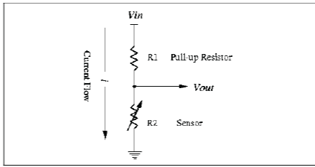
| Figure 2D represents the voltage divider circuit. It contains a
load resistor R1 of known value and a variable resistor R2
which keeps changing. Voltage division is the result of
distributing the input voltage among the components of the
divider. |
| A simple example of a voltage divider is two resistors
connected in series with the input voltage applied across the resistor pair and the output voltage emerging from the
connection between them. Since the two resistors are
connected in series, the current passing through each resistor at
every point is equal. |
| Ampere(R1) = Ampere(R2) |
| Ohm's law states that the current through a conductor between
two points is directly proportional to the potential
difference(voltage) across the two points. Introducing the
constant of proportionality, the resistance, one arrives at the
usual mathematical equation that describes this relationship: |
| V= IR |
| So the amount of current passing through resistor R1 can be
expressed as: |
| Ampere(R1) = V1/ R1 |
| Similarly the current passing through the resistor R2 can be
calculated in terms of voltage and resistance. The voltage in
resistor R2 is V2 which should be the reduction of voltage V1
from the input voltage. In other words the voltage through the
resistors R1 and R2 should sum up to the input voltage Vin.
Hence the current through the variable resistor R2 can be
calculated by |
| Ampere(R2)= (V2=Vin-V1)/ R2 |
| Since the amount of current passing though resistor R1 is equal
to the current passing through resistor R2 |
| V1/R1 = (Vin-V1)/R2 |
| Multiply with R2 on both sides gives: |
| R2*V1/R1 = (Vin –V1) |
| Divide by V1 on both sides gives: |
| R2/R1 =(Vin –V1)/V1 |
| The variable resistance of the gas sensor can be calculated
using the formula: |
| R2 = R1 * (Vin-V1) / V1 |
| Where R2 is the amount of resistance in the variable resistor.
Vin the input voltage and V1 is the voltage at load resistance
R1 (Table 1B). |
| The load resistance is used to accept electric current from a
source and causes a voltage drop when it is conducting a
current. With no load (open-circuited terminals), all of Vin falls across the output. However, the circuit will behave differently
if a load is added. The load resistance used in both MQ-2 and
MQ-7 sensor is 1 kohm. This gives good selectivity but
increasing the load resistance reduces the accuracy of the
concentration of the specific gas present in the air at very high
levels. |
Calibration |
| Calibration is a comparison between measurements-one of
known magnitude or correctness made or set with one device
and another measurement made in as similar a way as possible
with a second device. |
| The device with the known or assigned correctness is called the
standard. The second device is the device being calibrated. To
calibrate the sensors a known reference/standard value is used
and the known reference value changes according to the type
of sensor being used. |
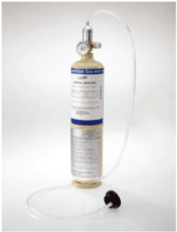
| Figure 2E depicts the calibration cylinder. The MQ-7 sensor
uses 100 ppm of Carbon Monoxide as the known reference
value and the MQ-2 sensor uses 1000 ppm of hydrogen as the
known reference value. The calibration procedure’s accuracy is based on this reference value and the whole procedure is only
as good as the known standard gas, as shown in figures 2F, 2G
and table 1C. |
| Using the resistance values obtained from the sensor and the
resistance of the known standard reference value a ratio is
calculated to co-relate with the concentration of the gas present
in air. The ratio is calculated using the formula R1/R0. Based
on the ratio values the concentration can be calculated in ppm
using the sensitivity characteristics of each sensor. |
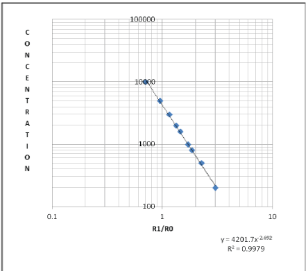
| Ordinate contains the resistance ratio of the sensor (R1/R0).
Abscissa is the concentration of gases in ppm. R1 is the
resistance of gases in different concentrations and Ro is the
resistance of sensor in the known standard reference 1000 ppm
of Hydrogen. Both the axes are of logarithmic values. The
power series equation =4201.7x^-2.692 for the chart is
obtained using the formula |
| Equation: y=c*x^b |
| c= EXP(INDEX(LINEST(LN(y),LN(x),,),1,2)) |
| b = INDEX(LINEST(LN(y),LN(x),,),1) |
| The LINEST function calculates the statistics for a line by
using the least squares method to calculate a straight line that
best fits the data, and then returns an array that describes the
line. LINEST function can be combined with other functions to
calculate the statistics for other types of models that are linear
in the unknown parameters, including polynomial, logarithmic,
exponential, and power series (Table 1D). The syntax of
LINEST function is |
| LINEST (known_y's, [known_x's], [const], [stats]) |
| known_y's -An array of y-axis values. |
| [known_x’s]-An optional argument providing an array of
known x-axis values. If provided the known_x’s array should
have the same number of values as the known_y’s array. If
omitted the array takes on the default values {1,2,3…} |
| [const]-An optional logical argument that determines how the
constant 'b' is treated in the power-line equation y =mx+b. This
argument can have the value TRUE or FALSE, If TRUE (or
omitted) the constant b is treated normally else if FALSE the
constant b is set to 0 in the equation. |
| [stats] -An optional logical argument which specifies whether
or not the function should return additional regression statistics
on the line of best fit. This argument can have the value TRUE
or FALSE, If FALSE (or omitted) then do not return additional
regression statistics i.e. just return the array of values mn,
mn-1, ... , b else if TRUE do return additional regression
statistics i.e. Return the array of values mn, mn-1, ... , b and
also return the additional regression statistics. |
| The LN function returns the natural logarithm of a number.
Natural logarithms are based on the constant e
(2.71828182845904). LN is the inverse of the EXP function
and the syntax of LN function is LN(number) where number is
the positive real number for which the natural logarithm is
required. |
| The INDEX function is used when it is needed to look a
reference to a cell within a single range. The syntax of the
function is |
| INDEX( array, row_num, col_num ) |
| Array -The specified array or range of cells |
| row_num - Denotes the row number of the specified array. If
set to zero or blank, this defaults to all rows in the supplied
array |
| col_num - Denotes the column number of the specified array.
If set to zero or blank, this defaults to all columns in the
supplied array |
| The EXP function returns e raised to the power of number. The
constant e equals 2.71828182845904, the base of the natural
logarithm. The syntax of the function is EXP(number) where
number is the real number which is used as the exponent. EXP
is the inverse of LN, the natural logarithm of number. To
calculate powers of other bases, the exponentiation operator (^)
is to be used. |
| EXP(8.343234) = =2.71828182845904^8.343234 = 4201.7. |
| The slope of the above line is -2.69208 and hence the power
line equation is given by y= 4201.7x^-2.69208. |
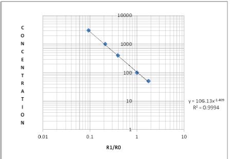
| Similarly in an mq-7 sensor ordinate contains the resistance
ratio of the sensor (R1/Ro). Abscissa is the concentration of gases in ppm. R1 is the resistance of gases in different
concentrations and Ro is the resistance of sensor in 100 ppm of
carbon monoxide in clean air. |
| The equation to find the concentration of carbon monoxide
present in air is given by y=106.13x^-1.409 (Table 1E). |
| The resistance of the sensor at 100ppm of carbon monoxide in
clean air is first calculated and this in turn is used to arrive at
the ratio R1/R0. The ratio on substitution in the power equation
gives the exact concentration of carbon monoxide present
(Figure 2G). |
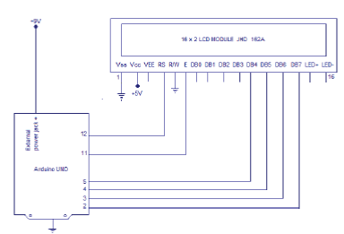
Lcd- arduino circuit |
| A 16X2 LCD display can display 2 lines of 16 characters each.
The display unit needs a regulated power supply of 5V. The
arduino contains a special library specifically for the LCD
display unit call the Liquid Crystal Library. It consists of many
in built functions which eases the access of the LCD display.
The connections between the arduino and the LCD display are
shown in the figure 2H. |
| The Liquid Crystal library allows an Arduino board to control
Liquid Crystal displays (LCDs) based on the Hitachi
HD44780or a compatible chipset, which is found on most textbased
LCDs. The library works with in either 4- or 8-bit mode
i.e. using 4 or 8 data lines in addition to the rs, enable, and,
optionally, the rw control lines. The Liquid Crystal Library
contains a set of functions which can turn on the display,
specify the characters to be displayed or printed specify the
cursor point at which the character is to be displayed. |
| Algorithm : Display concentration of gases in LCD |
| Input: Concentration from arduino |
| Output: Display in LCD |
| Step 1: Initialize LCD with LiquidCrystal Library. |
| Step 2: Create α(x) to access Liquid Crystal Library Functions. |
| Step 3: if(no_Param(α(x)==6)) |
| Use Liquid Crystal function with 6 param |
| Else |
| Use Liquid Crystal function with 7 param |
| Step 4: Initialize begin-> a(t): (16,2) |
| Step 5: Data: input concentration p(x) |
| Step 6: write->a(t): p(t) |
Gsm modem- Arduino circuit |
| The GSM modem can’t be powered using the arduino and
hence it draws its power from an external power source. It is
built in with a voltage regulator and hence it does not need any
regulation of power. |
| The GSM cannot be powered with a 9V battery because it
needs more than 1A of current during transmission. During
transmission the GSM modem needs high amount of current,
about 2A and hence the external power supply should be able
to provide it. |
| • Rx of arduino is connected to the Tx of GSM modem |
| • Tx of arduino is connected to the Rx of GSM modem |
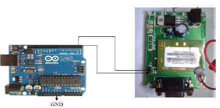
| Figure 2I represents GSM Modem to arduino connection. The
Arduino has to be uploaded with the code before is connected
to the GSM modem. The arduino board consists of two serial
ports called the Rx and Tx pin which is connected to the Tx
and Rx pins in the GSM modem respectively. The GND pins of
both the boards are also connected together. The Arduino
transmits the message to be sent using the serial ports. The
GSM on receiving the message to be sent fulfils the
transmission. The Arduino controls the GSM modem using AT
commands. The AT commands are written to the GSM modem
using the serial port [15,16]. |
| Algorithm : Provide GSM Alert to user along with their effects |
| Input: Concentration from Arduino |
| Output: SMS Alert |
| Step 1: Initialise GSM with AT commands |
| Step 2: Data : input concentration p(t) |
| Step 3: Set GSM to text mode AT+CMGS=1 |
| Step 4: Enter Mobile Number AT+CGMS=n(t) |
| If(μ(x) € >) |
| Enter Message Alert |
| Else |
| Re- enter n(t) |
| Step 5: nl(t) -> Ox1A to send SMS |
| The write function is used to send the controls and the data to
the GSM modem using the serial ports. It writes binary data to
the serial port. This data is sent as a byte or series of bytes. The
print function is used when the characters sent represent the
digits of a number. |
| Serial.write(0x0D); |
| A carriage return, sometimes known as a cartridge return and
often shortened to CR, <CR> or return, is a control character or
mechanism used to reset a device's position to the beginning of
a line of text. It is closely associated with the line feed and
newline concepts, although it can be considered separately in
its own right. It is represented using the hexadecimal digit 13. |
| Serial.write(0x0A); |
| A newline, also known as a line ending, end of line (EOL), or
line break, is a special character or sequence of characters
signifying the end of a line of text. The actual codes
representing a newline vary across operating systems, which
can be a problem when exchanging text files between systems
with different newline representations. It is represented using
the hexadecimal digit 10. The carriage return and line feed are
used together in a GSM modem to signal the end of a line and
beginning of another. |
| Table 1F shows the different concentrations of carbon
monoxide and its health effects. The GSM modem is used to
send the health effects which each concentration might bring to
the user. Based on the concentration messages can also be sent
to rescue workers. |
Results and Discussion |
| The system developed was able to work with a power supply
of 5V while most detectors need a minimum of 24V for proper
functioning. The life of sensor is also stable and with proper
calibration has a minimum lifetime of 5 years. |
| The response time for the system is 20-30 seconds and it does
not need any laboratory experiments to predict the
concentration of the gases present. The cross sensitivities of the
sensor is eased out through an intelligent system. |
| The system is designed in such a way the optimal working
conditions are the temperature and humidity of South India. Different working conditions would require different kind of
calibration procedure. |
| The concentrations of the gases were predicted with a high
level of accuracy and the deviation in percentage was less than
4% for carbon monoxide in low concentration of gases. In
methane the deviation is less than 10% for lower concentration
of gases. The deviation in percentage was found to be higher in
higher concentration of gases (Tables 2A and 2B). |
| The main advantages of the gas detecting system are that |
| It has a high level of accuracy. The accuracy in detection of
methane and carbon monoxide is very high. |
| It requires very less amount of power and can operate with a
power supply of 5V while other systems need a minimum of
24V. |
| The response time of the system is between 20-30 seconds.
The delay is typically set to avoid nuisance alarms. |
| Cross-Sensitivity is managed between methane and carbon
monoxide. |
| The detector can be made to go on monitoring the environment
while the workers are working due to the low amount of power
needed. |
Conclusion |
| The gas detection system was found to be highly accurate due
to the calibration procedure and it was able to detect carbon
monoxide and methane at the same time. The workers using
the detector not only get the concentration of the toxic gases
present in air but also the health hazards it could bring. The
concept of providing the user with the effects it could cause
eliminates the effect of illiteracy and carelessness. The system
provides the user with potential health hazards on continuous
exposure to a certain concentration of the gas [17,18]. |
| The system can be enhanced by increasing the number of gases
which can be detected by the detector. Thus system can be extended to multiple purposes and can be modified according
to the environment by adding or removing the sensors in the
system. Thus the detector would have the same goal of
detecting toxic gases but would find its applications in many
fields. The modularity of the system would be very high and
can be extended to various levels. |
Acknowledgement |
| We would like to express our thanks to the management of
Panimalar Engineering College for executing and validating
our proposed system. |
Tables at a glance |
 |
 |
 |
 |
| Table 1A |
Table 1B |
Table 1C |
Table 1D |
 |
 |
 |
 |
| Table 1E |
Table 1F |
Table 2A |
Table 2B |
|
| |
Figures at a glance |
 |
 |
 |
 |
 |
| Figure 1 |
Figure 2A |
Figure 2B |
Figure 2C |
Figure 2D |
 |
 |
 |
 |
 |
| Figure 2E |
Figure 2F |
Figure 2G |
Figure 2H |
Figure 2I |
|
| |
References |
- http://www.thehindu.com/opinion/op-ed/deaths-in-the- drains/article5868090.ece
- http://www.thehindu.com/todays-paper/tp-national/tp-tamilnadu/their-life-clogged-with-dangers/article1357153.ece
- Sharma S, Mishra VN, Dwivedi R, Das RR. “Quantification of individual gases/odors using dynamic responses of gas sensor array with ASM feature technique”. IEEE Sensors J 2014; 14: 1006–1011.
- Özmen A, Tekce F, Ebeoˇglu MA, Ta saltin C, Öztürk Z. Z. “Finding the composition of gas mixtures by a phthalocyanine-coated QCM sensor array and an artificial neural network”. Sens Actuators B Chem 2012;115: 450–454.
- Kumar R, Das RR, Mishra VN, Dwivedi R. “Wavelet coefficient trained neural network classifier for improvement in qualitative classification performance of oxygen-plasma treated thick film tin oxide sensor array exposed to different odors/gases”. IEEE Sensors J 2011; 11: 1013–1018.
- Gulbag A, Temurtas F. “A study on quantitative classification of binary gas mixture using neural networks and adaptive neurofuzzy inference systems”. Sens Actuators B Chem 2014; 115: 252–256.
- Capone S, Siciliano P, Bârsan N, Weimar U, VasanelliL.“Analysis of CO and CH4 gas mixtures by using a micromachined sensor array”. Sens Actuators B Chem 2011; 78: 40–48.
- Jing Li, Yingchun Shi, Wenhui Chang, Xufang Bo. “Application Research on Gas Detection with Artificial Olfactory System”. Sens Actuators 2012; 3: 233–254.
- Sharma S, Mishra VN, Dwivedi R, Das RR. “Classification of gases/odors using dynamic responses of thick film gas sensor array”. IEEE Sensors J 2013 13: 4924–4930.
- Khalaf W, Strangio MA. “Sensor array system for gases identification and quantification,”in Recent Advances in Technologies. Ed. Rijeka Croatia: InTech 2013.
- Lee D, Jung H, Lima J, Leeb M, Banb S, Huhc J. “Explosive gas recognition system using thick film sensor array and neural network”. Sens Actuators B Chem 2010; 71: 90–98,.
- Gutierrez-Osuna Ricardo. “Pattern Analysis for Machine Olfaction: AReview”. Microelectron J ieee sensors journal 2012; 2.
- http://arduino.cc/en/reference/homePage
- http://www.seeedstudio.com/depot/datasheet/MQ-2.pdf
- https://www.sparkfun.com/datasheets/Sensors/Biometric/MQ-7.pdf
- http://local.arduino.cc/bangalore/2014/08/04/interfacing-gsmsim300-with-arduino/
- http://spartacus-educational.com/FWWgas.htm
- http://www.labour.gov.hk/eng/public/oh/Drainage.pdf
|


