Research Article - Biomedical Research (2016) Computational Life Sciences and Smarter Technological Advancement
Development of arduino based low cost neuro-feedback applied to ADHD
Enas Abdulhay1*, Arwa Abdelhay2, Aya Kilani1, Lana Al-Shwiat1, Salam Al-Rousan1
1Faculty of Biomedical Engineering, Jordan University of Science and Technology, Irbid, Jordan
2Faculty of Natural Resources Engineering, German Jordanian University, Amman, Jordan
- *Corresponding Author:
- Enas Abdulhay
Faculty of Biomedical Engineering
Jordan University of Science and Technology Jordan
Accepted on April 06, 2016
Abstract
The main purpose of the presented paper is to implement a low-cost user-friendly neuro-feedback tool that can be used by children in underprivileged or developing countries in order to cope with Attention Deficit Hyperactivity Disorder (ADHD) via EEG signal analysis. First, the EEG is detected and analyzed with the help of an in-house designed and built system. The EEG signal spectrum is then divided into: Alpha, Beta, Theta and Gamma ranges. Second, the introduced work focuses on the analysis of power values related to Beta band of frequencies. Finally, the results of EEG analysis are exploited to switch on/off a game with the purpose of stimulation of child concentration.
Keywords
ADHD, EEG, Neuro-feedback, Beta wave, Arduino, Low cost.
Introduction
Electroencephalography (EEG)
Electroencephalography is a medical imaging technique that reads scalp electrical activity generated by brain structures. The EEG (Electroencephalogram) is defined as the electrical activity of alternating type recorded from the scalp surface after being picked up by metal electrodes and conductive media. Electroencephalographic reading is a completely noninvasive procedure that can be applied repeatedly to patients and neuro-typical adults/children with relatively no risk or limitation [1].
Electrodes placement and types
The system usually used to position electrodes for EEG monitoring is the International 10-20 system. Called 10-20 because of the way distances between electrode sites are computed. The distances between certain anatomically landmarks are segmented at increments of 10% and 20% of their value; and electrodes are placed at these points. A letter is used to indicate the area over which the electrode is located. Sites are identified as follows: P (parietal), F (frontal), T (temporal), O (occipital) [2]. Bipolar and mono-polar measurement types involve placement of two electrodes over specific brain regions and one electrode over one brain region, respectively. Proper functioning of EEG recording electrodes is critical for appropriate acquiring of high quality data. Many types of electrodes exist, often with different characteristics: reusable disc electrodes (gold, silver, stainless steel or tin), headbands with electrode caps, and saline-based electrodes. For accurate recording, the electrodes should be connected to lead-wires linked to an amplifier. The electrical potentials measured by the electrodes are conducted down the lead-wires, to the amplifier inputs, where they are amplified. When electrodes are used, the space between the electrode and the skin should be filled with conductive paste that ensures lowering of contact impedance at electrode-skin interface.
Brain waves
EEG spectrum can be subdivided into frequency bands [3]:
Delta waves (0.5-4) Hz: Delta waves tend to have the highest amplitude and the slowest frequencies. It is normally seen in adults in slow wave sleep and in newborns. It is usually most prominent frontally in adults and in posterior parts in children.
Theta waves (3-7) Hz: Theta waves occur mostly in the parietal and temporal regions. Theta occurrence is abnormal in alert adults but can be normal during sleep.
Alpha waves (8-13) Hz: Alpha waves can be noticed mainly from the occipital lobe but also from the parietal and frontal regions. They are produced when a person is in a conscious, relaxed state with closed eyes.
Beta waves (13- 30) Hz: Beta waves are acquired from the parietal, central and frontal lobes. They occur in alert or anxious states.
Attention Deficit Hyperactivity Disorder (ADHD)
Attention Deficit Hyperactivity Disorder (ADHD) is a behavioural disorder that starts during childhood. It starts before seven years old and lasts to adulthood. It affects 3-5% of children. Children, adolescents and adults with ADHD, have difficulty in concentrating. They often underperform in school and at work even though they are quite bright. They also suffer from poor self-esteem due to the way they learn. The primary characteristics of ADHD include inattention, impulsivity, and hyperactivity [4].
EEG characteristics of ADHD
ADHD can be characterized by differences in Theta and Beta (Sensory Motor Rhythm SMR, Beta, high Beta) waves. EEG, in ADHD, has slower and higher theta waves in frontal and central regions. The average excess is 32% [5]. It also does not include enough fast beta waves (15-18) in frontal, central and temporal regions [6,7]. Compared to neuro-typical subjects, amplitude of high Beta (22-30) is higher while amplitude of SMR (12-15) is lower [8,9].
Neuro-feedback process
Neuro-feedback is also called EEG Biofeedback because it is based on the electrical brain activity. Neuro-feedback is the training of self-regulation. Self-regulation leads to enhancement of the central nervous system function. In neurofeedback, electrodes are applied to the scalp to record brainwave activity. Afterwards, the issued signal is processed and the information about certain frequencies is extracted. Next, EEG is illustrated back to the child who should attempt to change the activity level: content related to some frequencies should be promoted while others should be diminished. The brainwave activity is hence "reshaped" toward a more “desirable” performance.
ADHD neuro-feedback protocol
Generally, therapists attempt simultaneously to increase the production of the fast wave activities (e.g., Beta and SMR) and to inhibit the excessive amplitude in the low and the high frequency activities: Theta (4-7 Hz) and high beta (22-30 Hz), respectively [10,11]. Nonetheless, a recent study pointed to an analysis concluding a weak link between Theta band and ADHD symptoms related to inattention. With a lack of income and a shortage of practitioners, children having ADHD in underprivileged or developing countries are in need for inexpensive access to brain exercises that reduce impulsivity and increase attentiveness. However, available devices on the market are expensive (from hundreds to thousands of dollars) and nessicetate presence of practitioners to assess issued reports. Our goal is hence to implement a simple low-priced neuro-feedback device that can be used by such citizens. The system aim is enabling the children suffering from ADHD to get a “better” EEG signal (healthier Beta) induced by the utilization of the proposed feedback method.
Material and Methods
The suggested tool consists of two parts: acquisition circuit and processor unit.
EEG acquisition circuit
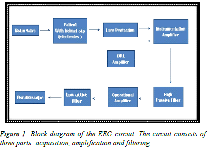
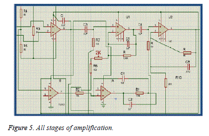
In this project, we used (Ag-AgCl) disc electrodes after cleaning the desired scalp locations with alcohol and applying conductive paste. Ag-AgCl electrodes are inexpensive that can accurately record very slow changes in potential. Used scalp electrodes consist of disks with leads connected to an amplifier. In frontal region, there is a risk of artefact caused by eye movement. Central locations (C3-C4 bi-polar placement) are therefore chosen [12]. As shown in Figure 1, the circuit consists of three parts: acquisition, amplification and filtering derived from [2,13-19]. The goal is to implement a portable battery-operated EEG amplifier with an appropriate bandwidth. Since the EEG has weak amplitudes, a plausibly high gain robust amplifier is required. The proposed circuit provides a gain up to 17000 and a 0.16-50 Hz bandwidth. Circuit pieces are simulated by Proteus software and implemented on a board. They are illustrated in the figures related to the following sections.
First stage of amplification/filtering
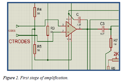
First stage of amplification (gain range 9-19) is achieved by the Instrumentation Amplifier (IA) INA114 which is suitable for medical applications, low cost, has a small size, offers excellent accuracy with low offset voltage, can operate with low power supplies and has a high common-mode rejection ratio. It is essential for the amplification of the bipolar difference of potential (C3-C4) detected by electrodes. In the suggested circuit, INA114 is controlled by the Rg (3.3 KΩ) value which is represented by the combination of R4 (5 KΩ) and R5 (5 KΩ) in parallel with R3 (5 KΩ) as indicated in Figure 2. The combination is connected to the pins 1 and 8 [6]. Since the feedback resistor between the first two internal amplifiers in the IA chip is 25 KΩ, the overall combination leads to the first step gain value: 16.
AIgain = 1 + [(2*25) / Rg]
= 1 + [50/((R3*Rs)/(R3+Rs))]
= 16 (1.1)
R4+R5=Rs
High pass passive filter-composed of resistor and capacitor components- is then connected to remove the DC offset voltage as indicated in Figure 2. The cut-off frequency is calculated as follows:
Fc = 1/ (2* П*R * C) (1.2)
Where R = R7 = 1 MΩ, and C = C3 = 1μF (Figure 2). Fc is therefore selected to be 0.16 Hz. This cut-off determines the lowest bandwidth frequency of the suggested circuit.
Second stage of amplification/filtering
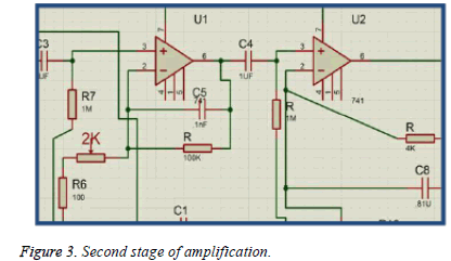
Second stage of amplification is achieved by an UA741. It is a general purpose operational amplifier featuring offset voltage null capability, high common mode input voltage range, absence of latch up and internal stability. The potential gain range is 48.6-1001. In the suggested circuit, a potentiometer (2 KΩ) is connected to UA741 in order to help amplify the signal [13]. Using a 2 KΩ potentiometer in series with a 100 Ω resistor-connected to the inverting pin 2-plus a feedback 100 KΩ resistor-connected to the pin 6- leads to a gain up to 51 as illustrated in Figure 3.
Gain = 1 + (Rfeedback/Rinverting) (2)
= 51
Rinverting = R6 + Rpotentiometer = 100 Ω + 2 KΩ
Rfeedback = R = 100 KΩ
A high pass filter is then connected (Figure 3) to remove the DC offset voltage which may result from second stage of amplification. The cut-off frequency determined by R and C4 is calculated using equation (1.2). Its value is 0.16Hz.
Third stage of amplification/filtering
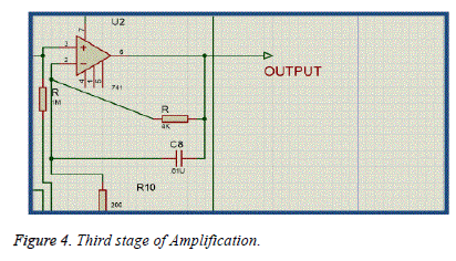
Third stage of amplification consists of a noninverting UA741 operational amplifier; it is an active low pass filter [2]. The chosen capacitor C8 and resistor R values are 4 KΩ and 0.81μF, respectively (Figure 4). The filter rejects therefore the frequencies higher than 50Hz. By substituting values of Rfeedback (R=4 KΩ) and Rinverting (200 Ω) in equation (2), the gain of the third stage of amplification is found to be 21(Figure 4).
All stages of amplification are illustrated in Figure 5.
Driven right leg circuit
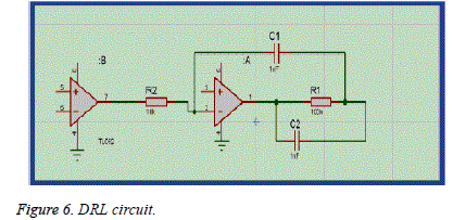
A DRL circuit diminishes the common mode interference noise as indicated in Figures 5 and 6. In the suggested circuit, two low power JFET input operational amplifier TL062 are utilized for DRL. It features high input impedance, low input bias current and low input offset current. In addition, it protects the user from the amplifier faults through limiting the current to a harmless level [13].
Power supply and reference
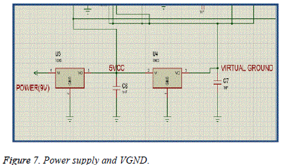
A 9V battery and a regulator have been utilized in the circuit. The regulator is necessary in cases of small oscillations in the input voltage. It leads to a 5V output voltage. In our work, the voltage regulator 7805 chip (Figure 7) has been employed. It is then connected (pin3) to a splitter 7905 that drives (0.5*5)V to a virtual ground and avoids unbalanced states [2,20,21] as indicated in Figure 7.
Finally, the analog output can be visualized by an oscilloscope.
Validation of EEG recording accuracy
The EEG signals recorded by the proposed circuit have been compared to recordings made by the onthe- market biomedical instrumentation kit SIP 385-1.
Processing part
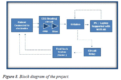
In ADHD, there is less Beta activity [22,23]. In our work, we established a Beta activity voltage threshold so that when the EEG Beta amplitude becomes lower than threshold a connected simple game is paused by the system. The overall processing system as shown in Figure 8 is composed of: good quality output signal issued from the previously detailed EEG Circuit, Arduino microprocessor, laptop and digital game. A programming stage has been achieved using Arduino IDE coding/library and MATLAB.
A/D convertor
After designing the acquisition circuit, there is a need For an A/D convertor in order to convert the analog output signal issued from our designed circuit into a digital form that can be transferred to the processing unit. An Arduino processor module has been employed for that purpose.
Arduino Microprocessor
Arduino is a low cost open source physical computing platform based on a simple input/output (I/O) board and a development environment that implements the processing language. Arduino can be used to develop stand-alone interactive objects as well as to convert measured data from analog to digital and send it to PC using (com 3). It Reads the value from the specified analog pin and converts it with a 10-bit analog to digital converter and resolution up to 4.9 mV per unit (Figure 8). It takes about 0.0001s to read an analog input. This yields maximum reading rate of about 9600 times per second. It is a pertinent choice to acquire accurate EEG signal according to Shannon Theorem. The Arduino chip reads the analog input on pin 0 and prints the result to the serial monitor. The chip pin A0 is connected to the center pin of a potentiometer and the outside pins to +5V and ground. In the presented work, Arduino chip has been programmed with the help of a PC via a USB cable. The open-source Arduino Software (IDE) with its rich library enabled to write the code and upload it to the board. MATLAB software has also been operated in order to visualize and to perform further analysis of digital recorded signals.
Volunteers
We have selected a number of volunteers: 5 children suffering from ADHD and 5 neuro-typical children Volunteers’ age range is (5-10) years. They all have medium to high IQ Level as shown in Table 1. Some of them went to special education school then attended conventional school while other still in special education schools. None has other chronic diseases. Parents of children and two practitioners were informed about the protocol accepted it and attended the recording sessions. The duration of every recording session is five minutes. Children were rewarded when they showed high concentration during the session.
| Volunteer | Age | IQ |
|---|---|---|
| 1 | 10 | GOOD |
| 2 | 7 | HIGH |
| 3 | 5 | HIGH |
| 4 | 6 | GOOD |
| 5 | 5 | HIGH |
Table 1: Characteristics table of the volunteers.
Determination of the threshold
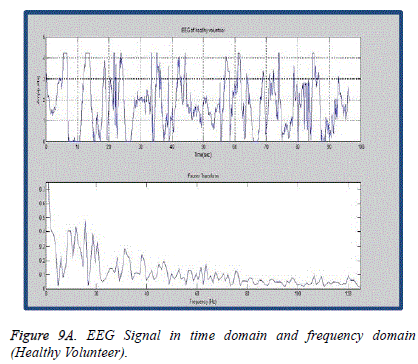
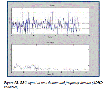
In order to determine the threshold we have compared between ADHD children and control group on the basis of EEG data amplitudes and spectra First, Fourier Transform is utilized to convert data from time domain to frequency domain.
The obtained spectra are then divided into EEG bands. Afterwards, only filtered EEG spectra portions related to the range 12-18 Hz have been studied because normal volunteer waves tend to be higher than ADHD brain waves in SMR and beta bands, and in order to cancel artifact.
The spectral power curve has been subsequently calculated through the squared Fourier Transform magnitude over a realtime moving window. The window length can be changed in the code according to the user. Finally, the area under the spectral power curve of Beta band was calculated via integration. Relative Power of Beta band (Beta power/ overall signal power) was used as the trigger of switching off a connected game.
The trigger is automatically activated when the relative power value decreases below a specific threshold. The threshold value has been experimentally studied in order to be inserted in the programming code taking into account the average and standard deviation of power area values.
Validation of spectral analysis accuracy
With the intention of verification of Arduino results, the EEG spectral power values resulted from the Arduino processor have been compared to values calculated by MATLAB signal processing toolbox.
Connecting a video game with Arduino
To complete the Feedback system, a low cost handheld video game console, with moderate CPU performance and resolution, has been connected to the Arduino chip via a relay component. In the suggested circuit and programming codes, if the ADHD child’s EEG data amplitude reaches the threshold or less at the frequencies 12-15 Hz or 15-18 Hz the game will stop working until the patient increases his/her focus ability to reach the amplitude peak of a neuro-typical child. Only at that point the game restarts.
Results and Discussion
Correlation coefficients and t-Student test results showed that the differences of EEG values, averages and standard deviations between the proposed circuit and the SIP 385-1 kit were negligible. Correlation coefficients and t-Student test results showed also that the differences of resulted EEG spectral power values between Arduino processor and MATLAB were negligible. By calculating the average power values in both SMR (12-15 Hz) and Beta (15-18 Hz) via Fourier spectrum as shown in Figures 9A and 9B, we found that the optimum experimental thresholds are 0.1654 and 0.0977, respectively .
The analysis results were injected in our feedback system. The patients EEG Beta levels switched the game on/off. A very slight improvement in Beta level has been observed after 5 sessions of neurofeedback. The results do not contradict with recent researches [10,12,21-23] but our system configuration was relatively simpler, much cheaper. This makes the proposed device user-friendly and affordable for any child who is diagnosed with ADHD but cannot pay the expenses of high priced sessions, instruments and follow-up by practitioners.
The cost of the latest candidate device (NEBA) for ADHD application approved by the US Food and Drug Administration (FDA) in July of 2013- is around 500$. In the present paper, the total cost of components in the suggested device is 90$. Thresholds in this paper are, similarly with other studies, predetermined and not adaptive. The system application was smoothly achieved. Patients were not bothered by it especially that the system is relatively portable and the game switching is not complicated.
During the recording sessions, situations where children demonstrated obvious distraction were directly automatically translated by the device into switching off the game. This reassured the parents about the sessions’ reliability. Nonetheless, many more sessions need to be followed in order to evaluate the final outcome of the suggested work. Children with ADHD have different EEG signal waves (Theta and Beta waves). Previous studies have focused on different bands (Theta and Beta, only Theta, only Beta, specific ranges of Beta) [10]. We have focused on differences in Beta wave rather than on other bands to treat inattention related to mental cognition processes abnormalities not to anxiety or to other factors, as proved in [24].
The five minute duration of every recording session has been established prior to EEG acquisition according to the recommendations of the practitioners’ supervisor who was engaged in the follow-up of the volunteers involved in the present study. The duration was chosen in order to avoid boredom feeling by the children and to motivate them to attend the following session. This helped us to make the child occupied by the tasks of the game without difficulty. However, this can be increased to the usual duration (20-50 minutes) set in biofeedback clinics.
Conclusion
Experimentally, ADHD children have been found to have less SMR and beta amplitudes than neurotypical ones with a border of specific thresholds. The proposed low cost accurate device is a promising tool for ADHD children with poor financial resources.
References
- Michal T. Fundamentals of EEG measurement. Measurement Sci Rev 2002; 2: 1-11.
- Noor AN, Nor HA. Portable EEG Signal Acquisition System. College Sci India 2009; 3: 1.
- Basar E, Basar-Eroglu C, Güntekin B, Yener GG. Brain's alpha, beta, gamma, delta, and theta oscillations in neuropsychiatric diseases: proposal for biomarker strategies. Suppl Clin Neurophysiol 2013; 62: 19-54.
- Brown TE, Reichel PC, Quinlan DM. Extended time improves reading comprehension test scores for adolescents with ADHD. Open J Psychiatry 2011; 1: 79-87.
- Sandra KL, Scott M. Clinical utility of EEG in Attention- Deficit/ hyperactivity Disorder: A research update. Neurotherapeutics 2012; 9: 569-587.
- Laub M, Leeuwen SPG. Individuals as measured by objective and self-Report measures of attention and impulsivity, when compared to a sham control condition, Master thesis, Utrecht University 2008.
- Mazaheri A, Fassbender C, Hartanto TA, Schweitzer JB, Mangun GR. Differential Oscillatory Electroencephalogram Between Attention-Deficit/Hyperactivity Disorder Subtypes and Typically Developing Adolescents. Bio Psychiatry 2014; 76: 422-429.
- Clarke AR, Barry RJ, McCarthy R, Selikowitz M, Brown CR. EEG evidence for a new conceptualisation of attention deficit hyperactivity disorder, Clin Neurophysiol 2002; 113: 1036-1044.
- Brown TE, Reichel PC, Quinlan DM. Executive function impairments in high IQ children and adolescents with ADHD. Open J Psychiatry 2011; 1: 56-65.
- Thomas FC. Technical foundation of neurofeedback. Routledge 1st ED, 2014.
- Ams M, de Ridder S, Strehl U, Breteler M, Coenen A. Efficacy of neurofeedback treatment in ADHD: The effects of Inattention, Impulsivity and Hyperactivity: Meta Analysis. Clin EEG Neuroscience 2009; 40: 180-189.
- Friel PN. EEG Biofeedback in the Treatment of Attention Deficit/ Hyperactivity Disorder. Alt Med Rev 2007; 12: 146-151.
- Noorazman NA, Hidayati N. Portable EEG Signal Acquisition System. J College Sci India 2009.
- Ramkumar B, Shenbaga DS. Assistive Device for paralyzed upper limbs using BCI. Int J Electrical Comput Eng 2015; 1: 21-24.
- Metting AC, Van-Rijn AP, Grimbergen CA. Amplifiers for bioelectric events: A design with a minimal number of parts. Med Biol Eng Comput 1994; 32: 305-310.
- Moulahcene F, Bouguechal NE, Belhadji Y. A Low Power Low Noise Chopper-Stabilized Tow-stage Operational Amplifier for Portable Bio-potential Acquisition Systems Using 90 nm Technology. Int J Hybrid Info Technol 2014; 7: 25-42.
- Benning M, Boyd S, Coshrane A, Uddenberg D. The Experimental Portable EEG/EMG Amplifier. University of Victoria Faculty of Engineering 2003.
- Sullivan TJ, Deiss R, Gert C. A Low-Noise, Non-Contact EEG/ECG Sensor. Biomedical Circuits and Systems Conference, 2007.
- Siddiqui MA, Siddiqui MM. EEG Signals and Its Recording Help In Different Disease. Int J Advance Res Sci Eng 2014; 3: 301-305.
- Metting AC, Van-Rijn A, Peper CA. Grimbergen, Instrumentation Amplifier for bioelectric events: a design with minimal number of parts. Med Biol Eng Comput 1994; 32: 305-310.
- Friel PN. EEG Biofeedback in the Treatment of Attention Deficit/ Hyperactivity Disorder. Alt Med Rev 2007; 12: 146-151.
- Jury DK, Grin-Yatsenko VA, Valery AP, Leonid SC, Elena AY, Inna SN. ERPs correlates of EEG relative beta training in ADHD children. Int J Psychophysiol 2005; 55: 23-34.
- David AK, Seigfried O. Effect of Neurofeedback on Variables of Attention in Large Multi-Center Trial. J Neurotherapy 2000; 4: 5-15.
- Thomas F, Niels B, Werner L, John HG, Jochen K. Neurofeedback Treatment for Attention-Deficit/Hyperactivity Disorder in Children: A Comparison With Methylphenidate. Appl Psychophysiol Biofeedback 2003; 28: 1-12.
