- Biomedical Research (2014) Volume 25, Issue 4
Detection of Diabetic disorders in the lower extremities: A cost effective screening device.
Pravin kumar S*, Subashini R, Ayesha Samreen, Deepthi G, Mythili S.Department of Biomedical Engineering, SSN College of Engineering, Rajiv Gandhi Salai (OMR), Kalavakkam, Chennai 603 110, India
- *Corresponding Author:
- Pravin kumar S
Department of Biomedical Engineering
SSN College of Engineering, Rajiv Gandhi Salai (OMR)
Kalavakkam, Chennai 603 110, India
Accepted date: August 10 2014
Abstract
This study describes a non-invasive cost effective screening tool for the diagnosis of lower extremity peripheral diabetic disorders that includes diabetic autonomic neuropathy (DAN), foot ulceration etc. The manifestation of these disorders is usually analyzed by measuring the pressure applied on the electrodes. In this study, we incorporated a new parameter namely the foot resistance. The electrodes pick up the subject’s foot skin resistance and the circuitry is used to display the resistance on the Liquid Crystal Display (LCD). A foot chart is created using the software Lab VIEW, which displays resistance variations in terms of color changes across the three regions of the foot. This device was evaluated on normal, diabetic and the subjects with diabetic neuropathy and the database thus obtained was analyzed.
Keywords
Diabetic neuropathy, foot resistance, loss of sensation, peripheral neuropathy, sweat function, sympathetic nervous system
Introduction
Diabetes mellitus resulted in an increased blood glucose level [1]. High blood sugar over a long time can damage the nerves, which in turn lead to loss of sensation. Lower extremities are most commonly affected. Some of the diabetic disorders include diabetic neuropathy, foot ulceration etc. These are generally diagnosed based on the symptoms. Also, there are various methods to diagnose the same by testing the loss of sensation [2].
One such method is the Filament test. Sensitivity to touch is tested using a soft nylon fiber, a 10g monofilament. If the patient is unable to feel the touch of the filament on his/her feet, it is a sign of loss of sensation in those nerves.
Another method is based on nerve conduction study. This includes the testing of how fast the nerves in the extremities conduct electrical signals. Sometimes electromyography is performed along with this test. Testing of the response of nerves to vibration is a common non-invasive method for diagnosis of diabetic neuropathy. This is performed using a 128Hz tuning fork.
The above-mentioned methods have their own limitations, either they are invasive or particularly used for diagnosis of peripheral neuropathy [3]. However, this study presents a new non-invasive technique to detect DAN using a cardinal parameter namely the foot resistance. The foot skin resistance is the moisture content in the foot, associated with the sweat glands activity, which is controlled by the sympathetic nervous system. Early diagnosis of DAN will lower the possibility of occurrence of foot ulcers [4] and amputation. Our study compared the change in foot skin resistance [5] between the normal subjects and patients with diabetic disorders. This is implemented using both hardware and software.
Methodology
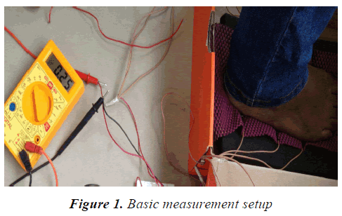
At the initial stage of the project, the skin resistance was measured using the standard set up i.e., the multimeter and the results were tabulated. We observed that there was a wide range of variations in the resistance values. The nonoccurrence of repeatability was the major drawback with the former method. Later, a model was developed to take realtime measurements from the subjects.
Prototype
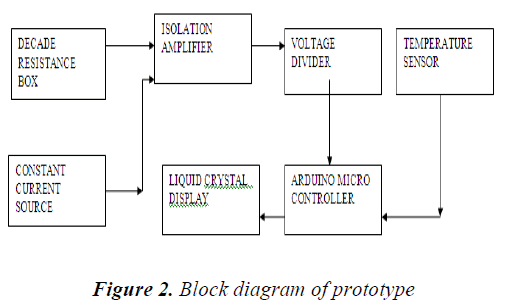
The prototype includes the calibration of circuit using standard resistance values obtained from the Decade Resistance Box (DRB). A dc constant current source circuit was designed to provide a constant current of 0.2mA as per the threshold of perception of a human skin. In addition to this, a voltage divider circuit [6] was designed as a resistance to voltage converter. The standard resistance arm of 100kO was used. The other arm of the circuit was connected to the DRB to obtain varied values across which the corresponding voltages were measured. The circuit has a temperature sensor to measure room temperature. The output values were displayed using the Arduino Micro-controller [7].
Subject model
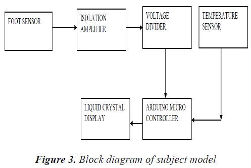
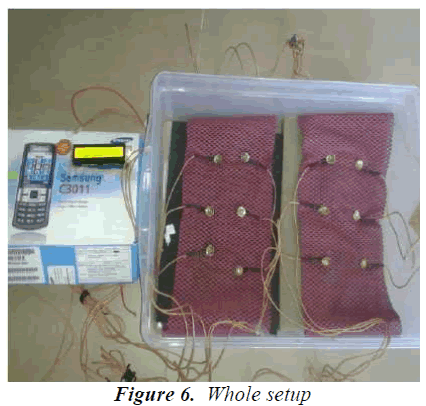
The subject model includes design of the foot sensor. A supply of 9V is given to the voltage divider circuit. One arm of the circuit was maintained at a very high resistance in order to limit the flow of current through the subject. The other arm of the circuit was connected to the output leads of the foot sensor and the corresponding voltages were measured. The foot resistance was then calculated from the obtained voltage values. The circuit also has a temperature sensor to measure the foot temperature [8]. The output values were displayed using the Arduino Micro- controller. This circuitry along with the foot sensor is placed inside a box in order to minimize the effects of environmental factors.
Design parameters
The foot resistance might vary mainly with respect to the surface area and moisture. This moisture content (sweating) depends on several parameters, including emotions, muscle activity, parasympathetic/sympathetic activity, room temperature, moisture content of the room.
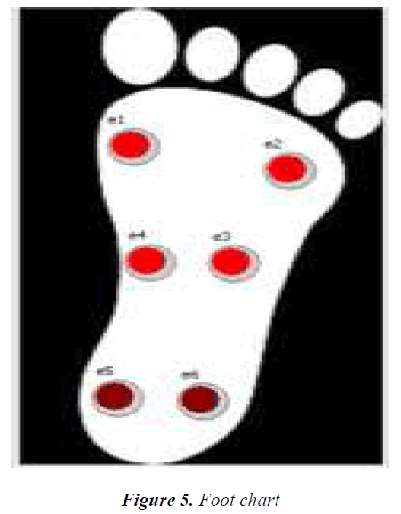
Environmental factors can be controlled by measuring the resistance in enclosed area under controlled temperature conditions. The constant monitoring of temperature is required to note the change of resistance with respect to change in temperature. The plot thus obtained can be used to distinguish the abnormal and normal subjects. The pressure applied on the electrodes can also vary the resistance and hence the subject is made to sit in a relaxed position with a clean foot. And the readings are continuously monitored for few minutes for accuracy. The electrodes are placed in such a way that it covers the three main regions of the foot-plantar region, ball region and the toe region. The surface area covered by the electrode also affects the resistance values. Hence a pliable electrode is to be used to get collective resistance values of the foot.
Hardware
The hardware includes the foot sensor, voltage regulator, voltage divider, temperature sensors and an Arduino microcontroller to interface with the Liquid Crystal Display. In addition to this, the isolation amplifier is designed for patient safety.
Voltage regulator
The voltage regulator [10] maintains constant voltage level and overcome power fluctuations. The IC 7805 used here provides a constant 5V output.
Voltage divider
The voltage divider circuit is used as a resistance to voltage converter.

Here R1 is considered as a standard resistor with a value of 100kO, R2 is the variable resistance obtained from the output leads of the foot sensor and Vin is the regulated voltage of 5V. In order to allow milli-ampere current to flow through the subject, the standard resistance is maintained at a higher value.
Isolation amplifier
The isolation amplifier provides electrical isolation and acts as electrical safety barrier. ISO122 protects the circuitry and subject from common mode voltages by capacitive isolation.
Temperature sensors
Two different temperature sensors are used here. One is to indicate room temperature and the other is used for measuring body temperature.
LM 35
LM35 measures the room temperature i.e., the temperature of the box within which the foot is placed. The output voltage obtained is proportional to the Celsius temperature. This IC does not require any external calibration. For every one degree rise in temperature there is a corresponding 10mV change.
Temperature strip
The temperature strip also known as the Fever Scan, an easy and safe method to measure the core body temperature. By holding the strip firmly against the surface for about 15s, the temperature can be read.
Foot sensor
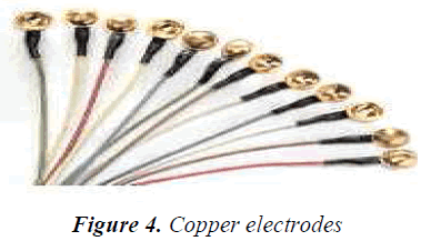
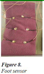
The foot sensor picks up the resistance from the different regions of the foot. They are placed according to the pressure [11] points from the three main regions ball, plantar and heal. The various electrodes, which were used are disposable ECG electrodes, suction type, copper clad plates and copper electrodes. The best among them are the copper electrodes and hence the same are used. Goldplated copper electrode provides good conductivity and covers smaller surface area. It ensures low-impedance interface to patient. Centre hole in cup allows for easy fill of electrode gel after adhesion of cup to skin. It provides better conductivity and reduced fluctuations compared to other electrodes.
Arduino microcontroller interfaced with LCD
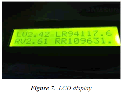
Arduino is a single board open source microcontroller (UNO-Atmel ATmega 328) interfaced with the LCD. The output voltage from the voltage divider is given as the input to the Arduino analog pin. The arduino is programmed to display the output voltage and the foot resistance picked up from both the right and left feet on the LCD.
Software
Lab VIEW [12] software is ideal for any measurement or control system, and the heart of the NI design platform. The DAQ assistant is used to acquire the real time AC or DC voltage. The foot sensors are connected to the DAQ assistant and the corresponding DC voltage signals are acquired.
Foot chart
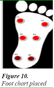
Lab VIEW was used to create a foot chart with colour box indicators to represent the placement of sensors on the subject’s foot and to show colour changes for varied foot resistances. Readings from three different regions of the foot viz., foot-plantar, toe and the ball regions were taken using the copper electrodes for the subjects. It was observed that colour variations were found among subjects with dry and wet skin.
It was also found that the resistance values from three different regions of a foot are not the same but varied to the slightest degree. This was used to effectively analyze the regions of foot with higher resistance values, which indicated the possibility of presence of disorders. This foot chart was also used to evaluate the degree of dysfunction in correspondence with the intensity of colour variations.
Implementation
The output of the DAQ assistant is converted into the required data type from the dynamic data type and is fed into the array. The first element of the array (Index Array Function) is extracted using the sub-array properties. Then the each index element obtained is given as input to the sub Vi. The sub vi consists of the round colour box properties. The colour box is programmed to display the corresponding colour code in accordance with the input resistance values.
Evaluation
The final device was tested for electrical safety prior to the real time measurements with the subjects.
Electrical safety analysis
The ultimate purpose of safety testing is to protect users from electric hazards. The electrical safety analyzer is used to test the leakage current between the electrodes and the ground of the circuit. Leakage current is the current that flows through the protective ground conductor to ground. In the absence of a grounding connection, it is the current that could flow from any conductive part or the surface of non-conductive parts to ground if a conductive path was available (such as a human subject). The subject places the foot on the electrodes through which there is a possibility of current entering the subject. The leakage current measured was around 50.7mA. The maximum permissible current is 100mA. Hence the equipment was found to be electrically safe.
Subjects
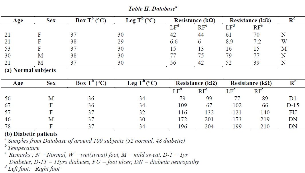
Ethical approval was obtained in order to recruit patients for real time measurement. For evaluation, a database of around 100 subjects (52 normal, 48 diabetic) was recorded. Foot resistance for various subjects including normal subjects, diabetic patients, long term diabetic patients, patients with foot ulceration and diabetic neuropathy were tabulated and analyzed.
Procedure
The environmental conditions and the muscular activities of the subject influence the moisture content of the skin i.e., sweating. These conditions can vary the foot resistance values drastically. Hence, the subject is made to sit in a closed environment and in order to adapt to the constant room temperature. This is measured using a temperature sensor. The feet are positioned on the electrodes inside a box, which is also maintained at constant temperature. Simultaneously, the foot temperature is measured using temperature strip. The foot resistance is recorded for a time period of 5 minutes. Any change in resistance within this period is taken into account.
Results and Discussion
The foot resistance values for normal subjects and patients with diabetes and diabetic neuropathy in particular were taken using the project setup referred in Table II. The following details were noted for each subject: name, age, sex, body temperature, ambient temperature (box temperature), resistance values for both the left and right feet, medical history namely diabetes/ DAN /leg pain/surgery underwent etc., and risk factors.
Hardware
It has been observed that the foot resistance showed relatively high value (greater than 100kO) for patients with diabetic neuropathy using our setup. When compared with the statistical study [5], our setup showed more accurate readings and therefore matched with the standard resistance range. Patients with foot ulcers, early stage of neuropathy and prolonged diabetes also showed high resistance values but less when compared to diabetic neuropathy. This was proven with the comparative analyses made between normal subjects and patients suffering from diabetic disorders. Normal subjects showed resistance values between 1kO to 100kO. However, a differentiation could be made among normal subjects with normal dry skin and wet (sweat) skin. Wet skin resistance was found to be from 1kO to 20kO depending on the degree of sweat whereas dry skin resistance was found to be between 20kO and 100kO for normal subjects.
A slight variation in foot resistance was also observed in accordance with body and ambient temperature. Only a mild degree of repeatability was obtained because of unstable human body conditions, which varied with the dayto- day activities. However, the readings taken from our setup for various subjects were within the standard range.
Software
With the foot chart created using Lab VIEW software, colour variations in accordance with foot resistance were studied. Readings from three different regions of the foot were taken using the copper electrodes for normal subjects. Explicit colour variations were found among dry and wet skin subjects. However, resistance values from three different regions of a foot were not the same but varied to the slightest degree.
Conclusion
Thus copper electrodes were placed at 6 different regions of the foot and the foot resistance values were recorded. A resistance to voltage converter circuit was implemented to simultaneously measured the corresponding voltage values. The resistance and voltage values were displayed on the Liquid Crystal Display controlled by an Arduino Microcontroller. A database of around 100 subjects was taken including the normal and the patients with diabetic disorder. It could be inferred that the foot resistance for patients with diabetic disorders were relatively high (>100kO) when compared to normals (1kO to 100kO). The equipment proved to be highly efficient and accurate.
This cost-effective device can be made portable in the form of a shoe that would provide comfort for the subjects being diagnosed. With such a design, gait analysis could be made and the resistance value for each stage of gait could also be studied. By increasing the number of electrodes covering the whole foot, a better cumulative resistance value could be obtained. This would be the focus of our future research.
Acknowledgments
The authors like to thank Dr.V.B.Narayana Murthy, Chief neurologist, Global hospitals for his invaluable help in producing the prototype.
References
- American Diabetes Association. Diagnosis and classification of diabetes mellitus. Diabetes Care 2012; 35:1
- Boulton AJM et al., Comprehensive Foot Examination and Risk Assessment. Endocrine Practice 2008; 14: 576-583
- Bruce AP, Olaleye D, Bernard Z, Bril V. Simple screening tests for Peripheral neuropathy in the diabetes clinic. Diabetes Care 2001: 24: 250-256
- Caselli A, Pham H, Giurini JM, Da, Armstrong DG, Veves A. The Forefoot-to-Rearfoot Plantar Pressure Ratio Is Increased in Severe Diabetic Neuropathy and Can Predict Foot Ulceration. Diabetes Care 2002: 25: 1066-1071
- Sun TB, Chien SH, Lee JT, Cheng LF. Electrical Resistance of Foot Skin in Diabetic Foot Patients. Formosan Journal of Surgery 2003; 34(2):78-82
- Sudhakar A, Shyammohan SP. Circuits and Networks Analysis and Synthesis. Technology and Engineering 3rd ed 2006, New Delhi: Tata McGraw Hill Education: 831pages
- Michael Margolis. Arduino Cookbook. Electronics 2nd ed 2011, O’Reilly Media,
- Roback K. An overview of temperature monitoring devices for early detection of diabetic foot disorders. PMID 2010; 7(5): 711-718.
- Boylestad RL, Nashelsky L, “Electronic Devices and Circuit Theory” in Electronics 9th ed 2006; New Delhi: Prentice-Hall.
- Foot Type And Plantar Pressure Measuring Device, by Ming-Jor Lo (2011, May 31). US Patent number US7950163/2011
- LabVIEW Data Acquisition Basic Manual. National Instrumentations, January 2000 edition

