Research Article - Biomedical Research (2019) Volume 30, Issue 1
A reliable method for morphological measurement of 3D calcaneus models from computed tomography images.
Irwansyah Idram1, Jiing-Yih Lai1* and Pei-Yuan Lee2
1Mechanical Engineering Department, National Central University, Taoyuan, Taiwan
2Chief of Orthopedic Department, Show Chwan Memorial Hospital, Changhua, Taiwan
- *Corresponding Author:
- Jiing-Yih Lai
Mechanical Engineering Department
National Central University, Taoyuan, Taiwan
Accepted date: January 29, 2019
DOI: 10.35841/biomedicalresearch.30-19-032
Visit for more related articles at Biomedical ResearchAbstract
The way to assess the calcaneal fractures reduction is still open. Anatomical morphology is an important clinical value to maintain normal function and may use as references to evaluate the reduction for calcaneal fractures. The aim of study is to provide reliable and repeatable three-dimensional (3D) morphology measurement. 3D models of ninety-nine Taiwanese normal calcaneus were reconstructed and segmented from CT image. Anatomical landmark serves as measurement constraints that manually identified and localized on bone mesh surface according to Gaussian curvature analysis. Computer assisted measurement and manual measurement were performed to quantify morphological parameters. Statistically, measurement results of calcaneal morphology were analyzed. The correlation between each of morphological parameters was tested using Bivariate-Pearson correlation. Gender differences relate to parameters were also tested. Intraclass correlation coefficient (ICC) and root mean square standard deviation (RMS-SD) were performed for reliable and precision study. Significant parameter differences between males and females were found (p<0.05). Yet, the correlation for each morphology parameters shows a strong correlation. Overall measurements show acceptable reliability and repeatability (ICC>0.754). RMS-SD of precision for linear and angular measurement was adequate, around 0.8 mm and 1.7°. Morphological parameters for both male and female groups, 78.5 mm in length, 42.1 in height, 43.3 mm in width, 112.5° in Gissane angle, 33.4° in Böhler angle, which is not much different compared to Asian morphology population. The proposed method positively contributes to measurement calcaneal morphology with significant reliability and repeatability. This study may offer to be a basic data and reference for assessment calcaneal fracture reduction.
Keywords
Three-dimensional measurement, Calcaneus morphology, Computed tomography, Anatomy landmark
Introduction
The calcaneus is one of the most frequently injured tarsal bone, with calcaneal fractures accounting for some 75% been intra-articular [1-3]. Different techniques have been reported in the literature to assess the clinical outcomes of calcaneal fractures. Traditionally, two-dimensional (2D) preoperative radiograph was compared with postoperative one to evaluate the treatment of bone fractures. Several researchers reported that the morphological parameters of the calcaneus include length, width, height, Gissane and Böhler angles, which may give the information of injured severity. Most of these parameters are evaluated with a measurement on a 2D planar radiograph or computed tomography (CT) images [4-6]. While, if the calcaneal parameters are directly measured on 2D images, the values will vary depending on the view of the scanning, rather than real anatomical landmarks. Moreover, it is hard to repeat and offer reliable measurement for the same patient. Other authors employed contralateral calcaneus, cadaver specimens, and 3D printed calcaneus to study clinical outcomes [7-10]. However, additional cost, an extra dose of radiation and ethical issues are significantly involved. The most accurate morphology measurement is to measure real bones directly on patients. However, it may be difficult to fulfill this approach as it requires high skill in operation and a large number of samples in the study [11,12].
By taking the advantage of medical imaging, analysis, and computational simulation as a part of computer-assisted technology, measurements of anatomical parameters in three-dimensional (3D) space have been implemented to obtain relevant information [13-16]. It allows calculating the surface, distance, and angle on a bone model that is directly generated from CT or magnetic resonance imaging (MRI). This measurement is accomplished by a computer-assisted method where the relevant parameters of calcaneal morphology are calculated by snapping the cursor onto specific points. The points or distinct regions are addressed on unique shape of the bone model (anatomical landmarks) manually palpable and geometrically recognizable. Yet, accurate identification and localization of the landmarks on the 3D bone model are tedious and time-consuming work. Unclear visibility of the unique points might be the reason for misleading localization and bringing to the uncertain placing of landmarks. Prior knowledge of anatomical landmarks is required as they are influenced by bone morphology. To improve the localization of landmarks, some authors applied the surface curvature-based approach to detect extreme points and geometric features from which the desired landmarks can be derived [17,18]. There appear to be not many studies on 3D measurement of calcaneus morphology with considering the accurate identification of anatomical landmarks.
In this study, a systematic approach to measure morphological parameters of the calcaneus is developed. We begin the method by reconstructing a 3D model of the bone directly from CT images, called 3D bone model herein. Anatomical landmarks are identified and placed on the surface 3D triangulated mesh. The surface curvature analysis method is specifically proposed to light the unique points or regions for easiness detection and identification. A method for resetting up the calcaneus model in 3D space due to the calcaneus is not scanned in the same position is addressed, which can yield consistency measurement of the morphological parameters. Finally, an automatic 3D measurement the morphological parameters for the calcaneus are performed using computer-assisted measurement. To verify the proposed method, manual measurement of 3D-printed calcaneus using digital vernier-caliper and optical compactor were performed. The aim of this study is to attain a 3D bone measurement method highly reliable and repeatable for measuring morphological parameters of the calcaneus in 3D space.
Materials and Methods
Materials
We studied 99 cases of healthy Taiwanese with no history of calcaneus disease. There were 49 males and 50 females in the age of 21-58, with an average of 37 years old. Age, height, weight, and BMI (body mass index) of all samples were also recorded as part of the morphological parameters of the calcaneus. All subjects were scanned using clinical CT (Siemens), with 0.2 mm slice interval between two cross-sectional images and size 512 × 512 pixels on each image. Thin-slice CT images of all subjects were saved in Digital Imaging and Communications in Medicine 3.0 format (DICOM, .dcm), and then input into a computer-assisted preoperative planning system for 3D model reconstruction.
Methods
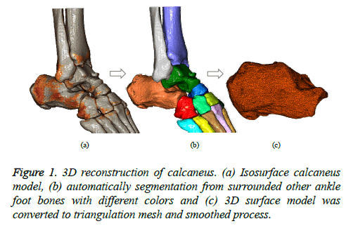
3D model reconstruction: A digitized 3D bone model was reconstructed from a series of CT images using a PC-based system of computer-aided preoperative planning tools. We developed the system using C++ language and DICOM ToolKit (DCMTK) library [19-20]. The system operates in a PC-based environment integrating virtual surgery simulation tools into a single computer program package (PhysiGuide v2.72.). Reconstruction of 3D bone models was performed on a consumer-grade personal computer (Intel® Core™ i5-4440 CPU, 3.1 GHz processor, 4 GB RAM, Windows 7 operating system). The system accepts thin slices CT images and displays 3D images with a volume rendering technique. A multi-region segmentation was employed to segment the bone tissue from other tissues. Then, smoothing and images processing were performed by adjusting threshold values. The processed images were used to reduce the error caused by noise and to enhance the boundary pixels before converted into a mesh model. The process of triangulation and correction was finally performed to yield the desired 3D bone model for further preoperative simulation and 3D printing of fractured bone fragments. Figure 1 depicts the 3D reconstruction of a calcaneus surrounded by other ankle foot bones. Different colors are assigned to distinguish each bone. After the calcaneus is selected, the triangulation and correction process is performed to yield the desired bone model. Hence, 3D model ready to use either for next simulation virtual surgery or fabricated using 3D printing technology.
In order to measure morphological parameters in space, users currently measure through several feature points snapped by cursors. Identifying accurate feature points on a bone surface is tedious and time-consuming. Also, determining precise feature points position is quite dependent on the user’s knowledge of anatomic landmarks. Moreover, positioning the feature points only based on interactive visual identification may lead to un-robust and un-repeatable measurement.
Localization anatomical landmarks: Taking the advantage of the uniqueness in shape characteristic of anatomic bones, the landmarks could be identified and localized conveniently and precisely. Currently, anatomical landmarks could be positioned in two ways, manual and automatic. Identifying and marking the bone model with manually placed landmarks corresponding to extreme regions is often used during the surgical procedure. User interactive approach is most commonly used for localizing landmarks on a bone model. Qiang et al. [13] proposed a procedure to manually mark landmarks on the calcaneal bone surface by an expert operator for measuring the morphological parameters. Liu et al. [21] presented a method for identifying landmarks which are guided by the curvature values on a 3D laser digitized foot model. Van [22] addressed the problem of manually positioning anatomical landmarks on a 3D bone model from MRI images for morphometric analysis. In summary, manual positioning of landmarks for morphological measurement is time-consuming, requires prior knowledge and high-level expertise of training. Also, it may lack in reliability and repeatability and is prone to errors.
For automatic landmark positioning, Jacinto et al. [23] and Ehrhardt et al. [24] proposed an algorithm for automatic positioning of landmarks based on a multi-atlas method on an anatomical structure. Subburaj et al. [17] identified the landmarks on a knee-bone model by detecting local landmark regions based on different surface curvature indicators. Even though, automatic landmark positioning on 3D bone models is still an active research issue. For localizing anatomic landmarks automatically, an approach based on 3D surface curvature analysis was employed to identify different geometric shapes, such as peak, ridge, pit, ravine and extreme points [17,18,23,24]. The accuracy of this approach strongly depends on the occurred errors during the reconstruction of the 3D bone model, smoothness and the triangulated-meshes model quality.
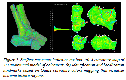
In this study, the overall process for identifying and localizing the anatomical landmarks of a calcaneus is shown in Figure 2. First, a 3D bone model is reconstructed and geometric errors during the mesh triangulation are corrected. Then, principal curvature directions and their derivatives are computed on every vertex of the bone model. The segregated vertices are mapped according to a Gaussian curvature and visualized as per vertex with the different color (Figure 2a). The principal component analysis (PCA) method is chosen to compute the principal direction of curvature. Surface fitting on volumetric data is used to compute the curvature of each vertex on the mesh model. Gaussian curvature is intrinsic quantity, depending only on the distances that are measured on the surface, not on the way it is embedded in Euclidean space [18]. The Gaussian curvature map can divide vertices into different regions that are differently colored so that anatomical landmarks can easily be identified and localized. Then, interactive technique was performed to localize the landmark points on 3D triangulated-mesh surface using Computer Aided Design (CAD) software. The anatomical landmarks of a calcaneus are marked with A to O, as shown in Figure 2b. The definition of each letter is described in Table 1 [13,25].
| Point | Descriptions |
|---|---|
| A | The highest point of the calcaneocuboid joint |
| B | The lowest point of the calcaneocuboid joint |
| C | The concave point in inferior surface of the calcaneus body |
| D | The lowest point of the calcaneal tuberosity |
| E | The highest posterior point of the calcaneal tuberosity |
| F | The highest point on the superior edge of the calcaneal tuberosity |
| G | The superior surface of the calcaneal body |
| H | The highest point of the posterior articular facet |
| I | The lowest posterior artic. facet at lateral surface intersecting anterior process |
| J | The medial surface of the calcaneal body |
| K | The lateral surface of the calcaneal body |
| L | The medial point on the posterior articular facet |
| M | The highest medial point on the sustentaculum tali |
| N | The highest lateral point on the sustentaculum tali |
| O | The lateral point on the posterior articular facet |
Table 1: Point Description of each letter.
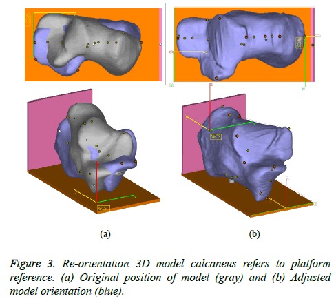
Normalizing position and orientation: The 3D models of different calcaneus subjects cannot directly be used in the measurement of morphology parameters as their poses are inconsistent during CT scanning. To set up a consistent measurement standard, it is necessary to reorient each model so that all of them can refer to the same reference. A platform reference was built as guidance to ensure consistent measurement of the morphology parameters on all subjects. Figure 3 shows the bone models of a calcaneus before reorientation (grey color) and after reorientation (blue color) with respect to a platform reference. To set-up the platform reference, we explored Melinska et al. [26] and Gutekunst et al. [27] works.
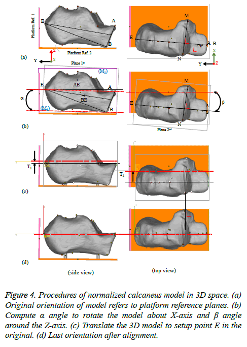
Figure 4 depicts the detailed procedures of reorienting the bone model. The initial condition of calcaneus model shows its main axes in angular and linear are not following to the platform reference axes, as shown in Figure 4a. For simplification, two relevant planes on calcaneus model are introduced to meet the plane orientation of platform references. The 1st plane on the calcaneus model was created by connecting three unique points A, B, and E. The 2nd plane was defined as a perpendicular plane of the 1st plane laying down on the anterior process. Angle a is the angle between the middle axis of 1st plane on calcaneus model and the middle axis of the reference platform plane in the horizontal direction. The angle a is calculated, and the calcaneus model is rotated around the x-axis direction according to angle a. Angle b is the angle between the middle axis of the 2nd plane and the middle axis of the reference platform plane in vertical direction. The angle b of calcaneus model is calculated and rotated around the z-axis direction. Figure 4b depicts an illustration of generating plane references and calculating a and b angles. Then, the calcaneus model displacement in linear distance along x and y direction also calculated (Figure 4c). The calcaneus model is translated to set the middle axis of the calcaneus models of the most posterior (point E) coinciding with the middle origin axis of the reference platform in x and y direction. Final position of the calcaneus model after resetting up the orientation is presented in Figure 4d.
Figure 4: Procedures of normalized calcaneus model in 3D space. (a) Original orientation of model refers to platform reference planes. (b) Compute α angle to rotate the model about X-axis and β angle around the Z-axis. (c) Translate the 3D model to setup point E in the original. (d) Last orientation after alignment.
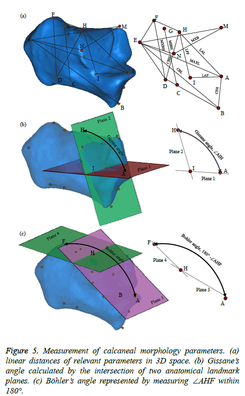
3D calcaneal morphology measurement: We assess the calcaneal morphology parameters following Qiang et al. [13] and Kim et al. [25], including linear distances (length, height, and width) and angles (Gissane’s and Bohler’s). These parameters were measured directly on the calcaneal model in 3D space. Before conducting the 3D measurement, the accurate and repeatable points (anatomical landmarks) were identified and localized to produce the relevant parameters. Seventeen calcaneus morphology were denoted as measurement parameters, as shown in Figure 5, where thirteen parameters are linear distances (6 lengths, 4 heights, and 3 breadth) and four parameters are angles (q, a, b, g), which are described in Table 2.
| Abbreviation | Measurement parameters | Descriptions |
|---|---|---|
| MAXL | Max. anteroposterior length | Linear distance between point A and E |
| CBL | Calcaneal body length | Linear distance between point B to E |
| MXBH | Maximum body height | Linear distance between point F and D |
| MIBH | Minimum body height | Linear distance between point G and C |
| CBH | Calcaneal body height | Linear distance between point H and D |
| LAL | Load arm length | Linear distance between point A and H |
| LPF | Length of posterior facet | Linear distance between point H and I |
| LAP | Length of anterior process | Linear distance between point A and I |
| CFH | Cuboidal facet height | Linear distance between point A and B |
| MXB | Maximum breadth | Linear distance between point M and N |
| MIB | Minimum breadth | Linear distance between point J and K |
| DAFB | Dorsal artic. facet breadth | Linear distance from point L to O |
| DAFL | Dorsal artic. facet length | Linear distance between point H and P |
| q | Gissane’s angle | Angular distance on points A, I and H |
| a | Böhler’s angle | Angular distance on 180° - Ð points AHF |
| b | Front angle | Angular distance from Ð planes BD and BF |
| g | Tuber angle | Angular distance from Ð planes BD and DF |
Table 2: Measurement parameters and their descriptions.
During the 3D measurement, two of relevant anatomic landmarks are selected. The two points can provide a segment for measuring and then two lines forming a space angle could be measured. The benefit of this approach is that the values of repetitive measurement can be ensured, and will not be affected by different views of objects. It also offers possibilities for the user to rotate and translate the calcaneal model in space with any viewing angle during the measurement. The measurement error may have occurred when snapping the cursor onto the landmark point; it should not be larger than 2 mm and 2º (diameter of the landmark point) [16]. Two consecutive of the landmark points were recognized to derive a line section for measuring a linear distance. In actual calculation, each of the landmark points has its own 3D coordinate system either in 2D or 3D view. So, for measuring linear distance only two landmark points of the calcaneal morphology parameter were considered. Instantly, the maximum length of the calcaneus anteroposterior (MAXL) is calculated according to the distance between point A and E, denoted as the center line of the calcaneus model (Figure 5a). For angle measurement, the angle between two planes that generated parallel to orthonormal vectors of the relevant axis of the landmark point was performed. Gissane angle is calculated based on the angle between plane 1 and 2 (Ðplane of AIH), as shown in Figure 5b. Plane 1 is the horizontal plane through the line of point A and point I that parallel to calcaneus center line and laying down on the anterior process. Plane 2 is the vertical plane connecting point I and point H, parallel to posterior talar articular surface. Böhler angle is the angle between two planes tangent (180º-Ðplane of AHF), as presented in Figure 5c. Angle plane of AHF is the angle between plane 3 (plane AH) and plane 4 (plane HF). Plane 3 is defined as a plane tangent to the line of the point A and H. Plane 4 is the plane tangent to the line through point H and point F. The measurement values were calculated automatically by computer software MAGICS 13 (Materialize Inc.). In order to verify the proposed method, we also measured the same morphological parameters directly on 3D-printed models by using a digital vernier-caliper and protractor.
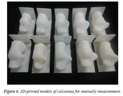
Verification of Measurement Method: Twenty calcaneus samples were selected randomly from ninety-nine samples and fabricated physically by using 3D printing technology, where ten of them are shown in Figure 6. All calcaneal models were fabricated layer by layer using a 3D-printer, (Lulzbot Taz 5, Aleph Objects Inc., USA). The slicing parameters of the 3D printing were set up by default software (LulzBot Cura, 21.04) to generate numerical controller (NC) tool paths. The filament material was Polylactic Acid (PLA) with a diameter of 2.85 mm. The parts were built by depositing the semi-molten material in form of layers with 0.2 mm constantly in each layer. Then, anatomic landmarks were manually marked on 3D-printed models similar to the location as in computer measurement. The landmarks were used to attain measurement reliability and reproducibility. A digital vernier-caliper (Mitutoyo absolute 500-196-20 digital caliper, 0-6" range, Mitutoyo Corp., Japan) and a protractor (Universal Bevel Protractor Mitutoyo absolute 187-101, Mitutoyo Corp., Japan) were used to measure the calcaneal morphology parameters directly on 3D-printed models.
Statistical analysis: The 3D measurement of morphological data was analysed using statistical package for the social science version 23.0 for windows software (SPSS Inc., IL, USA). Then all data of 3D measurement were analysed statistically. The gender differences including age, height, weight, and body mass index (BMI) in 3D morphological parameters were evaluated using the independent samples t-test. Normal distributed measurement data were represented with mean value, standard deviation for each morphological parameter.
The bivariate-Pearson correlation analysis was also employed to analyse the correlation between morphological parameters. In addition, paired samples t-test was performed to validate the proposed method by comparing the difference in 3D manual measurement and manual measurement. A p-value of less than 0.05 was considered statistically significant. Reliability of the morphological parameters was assessed using intra-class correlation coefficient (ICC). The root-mean square standard deviation (RMS-SD) was calculated and used to assess 3D measurement precision. In the RMS-SD equation, the SD calculation was only repeated once in which the measurement of the 99 subjects. The RMS-SD equation is shown below:
Results
Overall 3D morphological parameters of calcaneus and two different gender groups are shown in Table 3. Statistically, normal distributed measurement data were represented with mean value, standard deviation for each morphological parameter. Minimum and maximum morphological parameters were recorded to observe the deviation interval of measurements. There were significant differences in calcaneus morphology related to gender groups (P<0.05). In comparison to both groups, the average of calcaneal length (MAXL), height (MXBH), width (MXB), Gissane’s angle and Böhler’s angle were greater in the male group than those in the female group. The mean values of the remained parameters for males were slightly greater than those of females, except for the Böhler’s angle (a). T-test analysis was performed independently for each linear distance and angle for both male and female samples. The mean value of MAXL was (82.4 mm ± 4.3 mm) in male group and (73.8 mm ± 3.5 mm) in female group; the mean value of MXBH was (44.5 mm ± 2.8 mm) in male group and (39.7 mm ± 3.2 mm) in female group; the mean value of MXB was (45.9 mm ± 2.9 mm) in male group and (41.4 mm ± 3.3 mm) in female group; the mean Gissane’s angle was (112.9º ± 6.1º) in male group and (112.0º ± 5.4º) in female group; and mean value of Böhler’s angle was (33.9º ± 4.0º) in male group and (33.0º ± 4.0º) in female group.
| Subject parameters | Total (n-99) | Males (n=49) | Females (n=50) | |||||||||
|---|---|---|---|---|---|---|---|---|---|---|---|---|
| Mean ± SD | Range | p-Value | t-Value | Mean ± SD | Range | p-Value | t-Value | Mean ± SD | Range | p-Value | t-Value | |
| Age (years) | 37.3 ± 9.9 | 35.3-39.3 | 0.015 | 37.3 | 40.7 ± 8.2 | 21-58 | 0.503 | 34.5 | 33.9 ± 10.5 | 21-57 | <0.005 | 22.9 |
| Height (m) | 166.1 ± 8.1 | 150.5-185.0 | 0.336 | 204.9 | 165.5 ± 7.2 | 150-180 | 0.458 | 161.7 | 166.6 ± 8.9 | 150-185 | 0.362 | 132.4 |
| Weight (kg) | 67.2 ± 13.8 | 37.4-105.0 | 0.049 | 48.4 | 7.4 ± 14.5 | 43-105 | 0.134 | 32.6 | 66.9 ± 13.3 | 37-90 | 0.118 | 35.7 |
| Body Mass Index (BMI) | 24.2 ± 39 | 14.5-35.9 | 0.047 | 61.3 | 24.4 ± 4.1 | 18.3-35.9 | 0.071 | 42.1 | 23.9 ± 3.8 | 14.5-34.4 | 0.596 | 44.4 |
| MAXL=Max. length anteroposterior | 78.1 ± 5.8 | 65.2-91.4 | 0.271 | 133.2 | 82.4 ± 4.3 | 71.3-91.4 | 0.905 | 102.1 | 73.8 ± 3.5 | 65.2-83.1 | 0.950 | 87.5 |
| CBL=Calcaneous Body Length | 72.9 ± 5.8 | 60.8-86.8 | 0.089 | 124.7 | 77.2 ± 4.4 | 67.9-86.8 | 0.512 | 94.8 | 68.1 ± 3.7 | 60.8-78.2 | 0.721 | 82.3 |
| MXBH=Maximum Body Height | 42.1 ± 3.9 | 31.5-51.2 | 0.770 | 108.2 | 44.5 ± 2.8 | 38.8-51.2 | 0.369 | 81.9 | 39.7 ± 3.2 | 31.5-46.3 | 0.952 | 72.3 |
| MIBH=Minimum Body Height | 37.7 ± 3.3 | 28.6-45.5 | 0.396 | 114.6 | 39.9 ± 2.4 | 35.3-45.5 | 0.317 | 81.2 | 35.5 ± 2.4 | 28.6-42.2 | 0.438 | 81.3 |
| CBH=Calcaneus Body Height | 48.3 ± 4.3 | 37.6-58.2 | 0.727 | 111.9 | 51.2 ± 3.2 | 46.5-58.2 | 0.142 | 91.5 | 45.5 ± 3.2 | 37.6-52.1 | 0.748 | 70.5 |
| LAL=Long Arm Length | 39.2 ± 3.6 | 31.6-47.4 | 0.131 | 108.1 | 41.9 ± 2.7 | 34.9-47.4 | 0.546 | 82.2 | 36.7 ± 2.3 | 31.6-42.0 | 0.953 | 71.4 |
| LPF=Length of Posterior Facet | 25.6 ± 3.1 | 19.7-33.3 | 0.038 | 81.8 | 27.6 ± 2.6 | 22.8-33.3 | 0.338 | 60.9 | 23.5 ± 2.0 | 19.7-27.5 | 0.402 | 55.1 |
| LAP=Length of Anterior Process | 21.5 ± 2.6 | 16.7-27.9 | 0.458 | 82.3 | 22.3 ± 2.8 | 17.1-27.9 | 0.813 | 63.4 | 20.8 ± 2.2 | 16.7-25.7 | 0.413 | 53.9 |
| CFH=Cuboidal Facet Height | 23.2 ± 2.5 | 17.1-30.5 | 0.824 | 90.5 | 24.8 ± 2.2 | 19.6-30.5 | 0.503 | 61.1 | 21.7 ± 1.8 | 17.0-25.5 | 0.680 | 65.9 |
| MXB=Maximum breadth | 43.7 ± 3.9 | 36.1-52.1 | 0.072 | 111.1 | 45.9 ± 2.9 | 37.4-52.2 | 0.130 | 72.8 | 41.4 ± 3.3 | 36.7-49.3 | 0.168 | 84.7 |
| MIB=Mnimum breadth | 25.5 ± 2.8 | 19.9-32.7 | 0.200 | 88.8 | 26.9 ± 2.4 | 22.4-32.7 | 0.493 | 63.8 | 24.1 ± 2.6 | 19.8-32.7 | 0.031 | 62.1 |
| DAFB=Dorsal Articular Facet Breadth | 30.4 ± 3.2 | 23.1-41.0 | 0.800 | 93.4 | 32.1 ± 2.6 | 27.0-41.0 | 0.214 | 62.8 | 28.7 ± 2.8 | 23.1-35.4 | 0.018 | 68.9 |
| DAFL=Dorsal Articular Facet length | 26.3 ± 2.8 | 20.9-33.9 | 0.015 | 92.3 | 21.1 ± 2.5 | 22.0-33.9 | 0.156 | 62.9 | 24.8 ± 2.3 | 20.9-31.8 | 0.050 | 67.2 |
| ϴ=ÐAIH=Gissane's angle | 112.5 ± 5.1 | 101.4-127.1 | 0.156 | 194.2 | 112.9 ± 6.1 | 101.9-127.1 | 0.321 | 127.4 | 112.0 ± 5.4 | 101.4-125.7 | 0.398 | 147.7 |
| α=180°-ÐAHF=Bohler's angle | 33.4 ± 4.0 | 23.0-42.8 | 0.262 | 81.9 | 33.9 ± 4.0 | 25.2-42.8 | 0.491 | 55.9 | 33.0 ± 4.0 | 22.9-42.1 | 0.442 | 59.6 |
| β=Front angle | 36.8 ± 3.3 | 21.9-45.5 | 0.129 | 109.3 | 36.9 ± 3.3 | 21.9-42.3 | 0.013 | 94.3 | 36.5 ± 3.4 | 29.3-45.5 | 0.887 | 68.1 |
| γ=Tuber angle | 78.4 ± 3.8 | 69.8-86.9 | 0.293 | 201.9 | 78.3 ± 3.7 | 69.9-86.5 | 0.191 | 129.7 | 78.5 ± 3.9 | 70.3-86.9 | 0.772 | 162.6 |
Table 3: Three-dimensional morphological parameters of calcaneus in different gender groups.
The Bivariate-Pearson correlation analysis was performed for all morphological parameters including age and BMI. The correlation analysis results for both male and female groups are presented in Table 4. The results of male group were as follows: age was significantly correlated with length MAXL (r=-0.437, p<0.01), CBL (r=-0.396, p<0.01), CFH (r=-0.463, p<0.01) and g angle (r=-0.372, p<0.01). However, BMI was not significantly correlated with all parameters. Length (MAXL) was strong significantly correlated with CBL (r=-0.907, p<0.01), MXBH (r=-0.509, p< 0.01), MIBH (r=-0.485, p<0.01), CBH (r=0.607, p<0.01), LAL (r=0.528, p<0.01), LPF (r=0.367, p<0.01), LAP (r=0.397, p<0.01), CFH (r=0.599, p<0.01), MIB (r=0.607, p<0.01), and DAFB (r=0.531, p<0.01). Height (MXBH) was significantly correlated with MIBH (r=0.722, p<0.01), CBH (r=0.568, p<0.01), CFH (r=0.390, p<0.01), MIB (r=0.395, p<0.01), and b angle (r=0.498, p<0.01). Width (MXB) was only significantly correlated with MIB (r=0.374, p<0.01) and DAFB (r=0.443, p<0.01). Gissane’s angle (q) and Böhler’s angle (a) were not correlated with other parameters. The correlation analysis results of female group were as follows: age was only significantly correlated with BMI (r=0.421, p<0.01). BMI was not significantly correlated with other parameters. Length was strong significantly correlated with distance parameters except for all angle parameters. Height (MXBH) was significantly correlated with MIBH (r=0.792, p<0.01), CBH (r=0.719, p<0.01), LAL (r=0.378, p<0.01), MXB (r=0.384, p<0.01), and b angle (r=0.778, p<0.01). Width (MXB) was significantly correlated with MIB (r=0.543, p<0.01), DAFB (r=0.492, p<0.01), and DAFL (r=0.485, p<0.01). Gissane’s angle (q) and Böhler’s angle (a) were not correlated with other parameters.
| Male (n=49) | ||||||||||||||||||||
| Age | BMI | MAXL | CBL | MXBH | MIBH | CBH | LAL | LPF | LAP | CFH | MXB | MIB | DAFB | DAFL | ϴ | α | β | γ | ||
| Female (n=50) | Age | 0.043 | -0.437** | -0.396** | -0.181 | -0.242 | -0.285* | -0.325* | -0.149 | -0.285* | -0.463** | -0.16 | -0.218 | -0.22 | -0.339* | -0.016 | -0.058 | 0.258 | -0.372** | |
| 0.767 | 0.002 | 0.005 | 0.213 | 0.094 | 0.047 | 0.023 | 0.308 | 0.047 | 0.001 | 0.273 | 0.133 | 0.129 | 0.017 | 0.912 | 0.691 | 0.074 | 0.008 | |||
| BMI | 0.421** | 0.128 | 0.14 | -0.004 | 0.222 | 0.028 | -0.022 | 0.24 | -0.158 | 0.186 | 0.157 | 0.005 | 0.224 | -0.57 | -0.143 | -0.055 | -0.085 | 0.205 | ||
| 0.002 | 0.382 | 0.338 | 0.979 | 0.125 | 0.846 | 0.879 | 0.097 | 0.277 | 0.201 | 0.28 | 0.974 | 0.121 | 0.699 | 0.326 | 0.71 | 0.562 | 0.157 | |||
| MAXL | 0.051 | 0.186 | 0.907** | 0.509** | 0.485** | 0.607** | 0.528** | .367** | 0.397** | 0.599** | 0.242 | 0.381** | 0.531** | 0.299** | -0.068 | -0.191 | -0.088 | -0.128 | ||
| 0.723 | 0.195 | 0 | 0 | 0 | 0 | 0 | 0 | 0.005 | 0 | 0.094 | 0.007 | 0 | 0.037 | 0.64 | 0.19 | 0.55 | 0.379 | |||
| CBL | 0.144 | .315* | 0.872** | 0.512** | 0.410** | 0.600** | 0.358* | 0.27 | 0.229 | 0.437** | 0.244 | 0.300* | 0.403** | 0.277 | -0.017 | -0.184 | -0.128 | -0.205 | ||
| 0.32 | 0.026 | 0 | 0 | 0.003 | 0 | 0.012 | 0.061 | 0.114 | 0.002 | 0.091 | 0.036 | 0.004 | 0.054 | 0.908 | 0.206 | 0.38 | 0.159 | |||
| MXBH | 0.217 | 0.203 | 0.433** | 0.419** | 0.722** | 0.568** | 0.226 | 0.227 | 0.141 | .390** | 0.320* | 0.391** | 0.338* | 0.208 | -0.09 | -0.262 | 0.498** | -0.048 | ||
| 0.131 | 0.157 | 0.002 | 0.002 | 0 | 0 | 0.118 | 0.116 | 0.334 | 0.006 | 0.025 | 0.005 | 0.017 | 0.152 | 0.537 | 0.069 | 0 | 0.746 | |||
| MIBH | -0.023 | 0.193 | 0.490** | 0.404** | 0.792** | 0.594** | 0.28 | .409** | 0.102 | 0.605** | 0.277 | 0.433** | 0.536** | 0.202 | -0.186 | -0.071 | 0.388** | 0.249 | ||
| 0.874 | 0.18 | 0 | 0.004 | 0 | 0 | 0.052 | 0.003 | 0.485 | 0 | 0.054 | 0.002 | 0 | 0.165 | 0.201 | 0.63 | 0.006 | 0.084 | |||
| CBH | 0.149 | 0.135 | 0.478** | 0.403** | 0.719** | 0.579** | 0.181 | 0.225 | 0.217 | 0.493** | 0.282** | 0.26 | 0.375** | 0.144 | -0.215 | 0.203 | 0.208 | -0.165 | ||
| 0.301 | 0.348 | 0 | 0.004 | 0 | 0 | 0.214 | 0.12 | 0.134 | 0 | 0.05 | 0.071 | 0.008 | 0.325 | 0.139 | 0.163 | 0.151 | 0.258 | |||
| LAL | 0.023 | 0.14 | 0.692** | 0.542** | 0.378** | 0.540** | 0.209 | 0.556** | 0.487** | 0.397** | 0.141 | 0.328* | 0.225 | 0.336* | 0.254 | 0.174 | -0.055 | -0.07 | ||
| 0.875 | 0.334 | 0 | 0 | 0.007 | 0 | 0.145 | 0 | 0 | 0.005 | 0.335 | 0.021 | 0.121 | 0.018 | 0.079 | 0.232 | 0.708 | 0.63 | |||
| LPF | -0.037 | 0.233 | 0.497** | 0.376** | 0.305** | 0.458** | 0.062 | 0.734** | -0.216 | 0.274 | 0.23 | 0.319* | 0.317** | 0.427** | -0.179 | 0.127 | 0.003 | -0.109 | ||
| 0.8 | 0.103 | 0 | 0.007 | 0.031 | 0.001 | 0.667 | 0 | 0.137 | 0.056 | 0.112 | 0.026 | 0.026 | 0.002 | 0.218 | 0.385 | 0.983 | 0.455 | |||
| LAP | 0.248 | -0.35 | 0.449** | 0.300* | 0.227 | 0.245 | 0.410** | 0.445** | 0.077 | 0.297* | -0.011 | 0.065 | 0.118 | 0.026 | -0.124 | 0.089 | 0.046 | 0.015 | ||
| 0.083 | 0.81 | 0.001 | 0.034 | 0.112 | 0.087 | 0.003 | 0.001 | 0.595 | 0.038 | 0.939 | 0.656 | 0.418 | 0.859 | 0.397 | 0.542 | 0.751 | 0.917 | |||
| CFH | -0.22 | -0.033 | 0.427** | 0.273 | 0.330* | 0.446** | 0.369** | 0.284* | 0.349** | 0.157 | 0.262 | 0.238 | 0.413** | 0.197 | -0.106 | -0.068 | -0.083 | 0.294* | ||
| 0.124 | 0.823 | 0.002 | 0.055 | 0.019 | 0.001 | 0.008 | 0.045 | 0.013 | 0.276 | 0.069 | 0.099 | 0.003 | 0.174 | 0.469 | 0.641 | 0.57 | 0.04 | |||
| MXB | -0.023 | 0.068 | 0.491** | 0.510** | 0.384** | 0.472** | 0.455** | 0.355* | 0.318* | 0.209 | 0.361* | 0.374** | 0.443** | 0.361* | -0.142 | 0.004 | -0.143 | 0.021 | ||
| 0.876 | 0.639 | 0 | 0 | 0.006 | 0.001 | 0.001 | 0.011 | 0.025 | 0.144 | 0.01 | 0.008 | 0.001 | 0.011 | 0.33 | 0.98 | 0.326 | 0.887 | |||
| MIB | 0.101 | 0.13 | 0.445** | 0.370** | 0.361* | 0.292* | 0.434* | 0.214 | 0.228 | 0.158 | 0.097 | 0.543* | 0.642** | 0.503** | 0.055 | -0.099 | -0.016 | 0.086 | ||
| 0.483 | 0.367 | 0.001 | 0.008 | 0.01 | 0.04 | 0.002 | 0.136 | 0.112 | 0.274 | 0.501 | 0 | 0 | 0 | 0.707 | 0.497 | 0.914 | 0.556 | |||
| DAFB | 0.021 | 0.316* | 0.463** | 0.324** | 0.345* | 0.436** | 0.462** | 0.294* | 0.476** | 0.186 | 0.257 | 0.492** | .635** | 0.366** | -0.173 | -0.087 | -0.019 | 0.157 | ||
| 0.883 | 0.025 | 0.001 | 0.022 | 0.014 | 0.002 | 0.001 | 0.038 | 0 | 0.196 | 0.071 | 0 | 0 | 0.01 | 0.234 | 0.552 | 0.895 | 0.282 | |||
| DAFL | 0.043 | 0.319* | 0.501** | 0.391** | 0.345** | .498** | 0.385** | .444** | 0.477** | 0.023 | 0.249 | 0.485** | 0.529** | 0.629** | -0.147 | -0.031 | -0.103 | -0.061 | ||
| 0.767 | 0.024 | 0 | 0.005 | 0.014 | 0 | 0.006 | 0.001 | 0 | 0.874 | 0.081 | 0 | 0 | 0 | 0.314 | 0.83 | 0.483 | 0.677 | |||
| ϴ | -0.21 | 0.062 | 0.084 | 0.16 | -0.052 | 0.078 | -0.231 | 0.227 | 0.022 | -0.429** | -0.048 | -0.031 | -0.201 | -0.183 | -0.035 | 0.063 | -0.134 | -0.02 | ||
| 0.143 | 0.667 | 0.561 | 0.267 | 0.719 | 0.59 | 0.106 | 0.113 | 0.882 | 0.002 | 0.741 | 0.832 | 0.162 | 0.203 | 0.809 | 0.667 | 0.359 | 0.891 | |||
| α | 0.058 | -0.095 | -0.202 | -0.176 | -0.047 | -0.031 | 0.27 | -0.114 | -0.236 | 0.166 | -0.258 | 0.111 | -0.121 | 0.052 | -0.051 | -0.041 | -0.081 | -0.119 | ||
| 0.688 | 0.51 | 0.16 | 0.221 | 0.747 | 0.832 | 0.058 | 0.431 | 0.099 | 0.249 | 0.071 | 0.442 | 0.403 | 0.719 | 0.725 | 0.779 | 0.582 | 0.414 | |||
| β | 0.123 | 0.11 | -0.036 | -0.137 | 0.778** | 0.562** | 0.582** | -0.001 | 0.032 | 0.02 | 0.081 | 0.075 | 0.237 | 0.243 | 0.218 | -0.184 | 0.065 | -0.033 | ||
| 0.394 | 0.447 | 0.805 | 0.344 | 0 | 0 | 0 | 0.995 | 0.825 | 0.891 | 0.576 | 0.607 | 0.098 | 0.089 | 0.128 | 0.202 | 0.652 | 0.823 | |||
| γ | 0.011 | 0.009 | 0.043 | 0.041 | -0.027 | 0.073 | 0.008 | 0.215 | 0.301* | -0.019 | 0.280* | 0.044 | -0.018 | 0.173 | 0.16 | 0.09 | -0.048 | -0.18 | ||
| 0.939 | 0.951 | 0.767 | 0.777 | 0.851 | 0.615 | 0.954 | 0.134 | 0.034 | 0.897 | 0.049 | 0.761 | 0.899 | 0.23 | 0.268 | 0.536 | 0.741 | 0.211 | |||
| *p<0.05, **p<0.01 (the bold text is p-value, and the regular text is Pearson Corrrelation Coefficient) | ||||||||||||||||||||
Table 4: Bivariate-Pearson correlation analysis of calcaneal morphology parameters for 99 cases [28].
The intra-observer reliability of the main morphological parameters presents ICC values range from 0.739 to 0.997. The calcaneus distances reliability of the MAXL (0.987 to 0.997) was greater than the reliability of the MXBH (0.893 to 0.956), and the MXB (0.809 to 0.873). For calcaneus inclination angles, the reliability of the Gissane’s angle (0.127 to 0.136) is lower than Böhler’s angle (0.739 to 0.745) due to the difficulty in precise measurement. The intra-observer RMS-SD of the 3D calcaneus morphology measurements, MAXL, MXBH, MXB, Gissane’s angle, and Böhler’s angle was calculated. The RMS-SD values for linear distances and angles were lower than 0.8 mm and 1.7°, respectively.
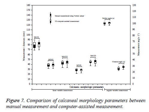
Paired t-test was performed for computer-assistive measurement on the 3D model and manual measurement on the 3D-printed calcaneus. Statistical analysis results show that p values for each parameters, MAXL (p=0.026), MXBH (p=0.022), CBH (p=0.002), LAL (p=0.001), CFH (p=0.016), q angle (p=0.000), a angle (p=0.012), and g angle (p=0.000) were less than 0.05 (p<0.05). Jamali et al. [16] reported that the computer-assisted measurement would be valid and accurate within a threshold 2 mm or 2º compared to a gold standard. The probability of parameter differences in the two methods is not significant. Therefore, the computer-assisted measurement can be used to replace manual measurement. Figure 7 presents the comparison of morphological parameters results for both manual and computer-assisted measurements. It indicates that those parameters were not significant difference under the two measurements. Therefore, computer-assisted measurement can be used to substitute manual measurement.
Discussion
Calcaneal fractures are the most commonly injured tarsal bone. They are usually caused by axial loading trauma, as from a fall or a motor vehicle accident. About 60-75% of all calcaneal fractures are displaced intra-articular fractures. Several related works on calcaneus fractures suggest that a better reduction provides better outcome results. Pre- and post-operative radiographs were often used as a tool to assess bone fracture.
